George Henry
-
Trevor Thompson
- Driver

- Posts: 1190
- Joined: Fri Oct 05, 2018 6:30 pm
- Location: South West Wales
George Henry
I have picked up a project I abandoned about 8 years ago - really because I didn't know enough to make it work. It came about after building a 16mm scale "Idris", and I really wanted to make it again - but much closer to the original in appearance and function.
So photos of where I got to:
My original attempt at Stephenson valve gear in the confined space sort of worked but bits of the motion kept breaking. So it was abandoned. It distracted me from track building last week, and the video of the result is at https://www.dropbox.com/scl/fi/awj46nxb ... akwe8&dl=0
I will share details of its workings later, and follow on as I finish it.
Trevor
So photos of where I got to:
My original attempt at Stephenson valve gear in the confined space sort of worked but bits of the motion kept breaking. So it was abandoned. It distracted me from track building last week, and the video of the result is at https://www.dropbox.com/scl/fi/awj46nxb ... akwe8&dl=0
I will share details of its workings later, and follow on as I finish it.
Trevor
-
Trevor Thompson
- Driver

- Posts: 1190
- Joined: Fri Oct 05, 2018 6:30 pm
- Location: South West Wales
Re: George Henry
When I came back to this I started to find the errors that I had made the first time around. Firstly the cranks and eccentrics on the axle were loose. So the first thing was to cut the axle apart (to reuse the wheels) and remake it.
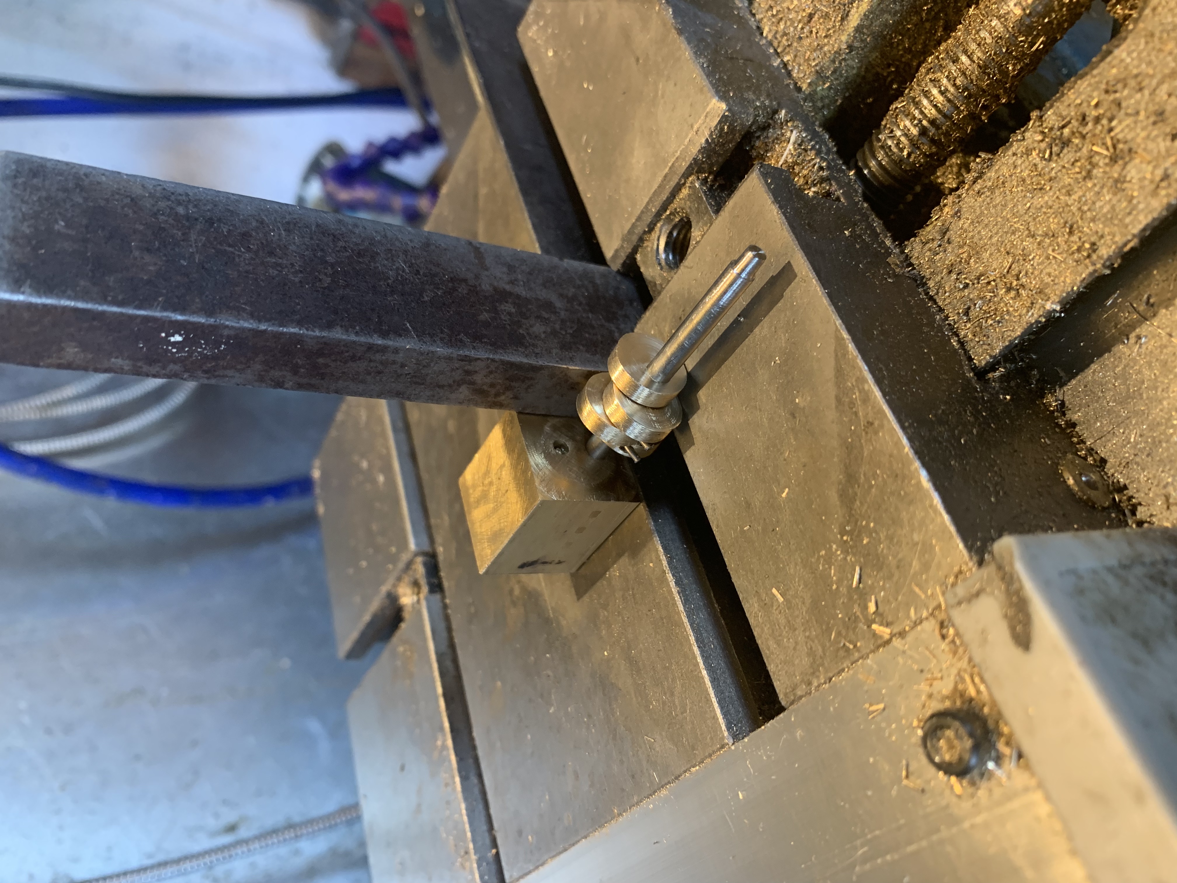
To get the Stephenson valve timing correct I made a jig to set the eccentrics onto the axle. It consists of a block of brass with a hole in it. The distance between the hole and the edge is slightly less than the radius of the eccentrics, so that when assembled the valve will open just after the piston reaches the end of its travel. So the jig sets the 2 eccentrics on the axle, offset not 180 degrees apart, but about 170 degrees apart. Using the jig, the lathe carriage and a set square the two sets of eccentrics are set 90 degrees from each other, and as in this photo :
In a similar way the crank can be set at 90 degrees to the eccentrics.
This is the axle assembled:
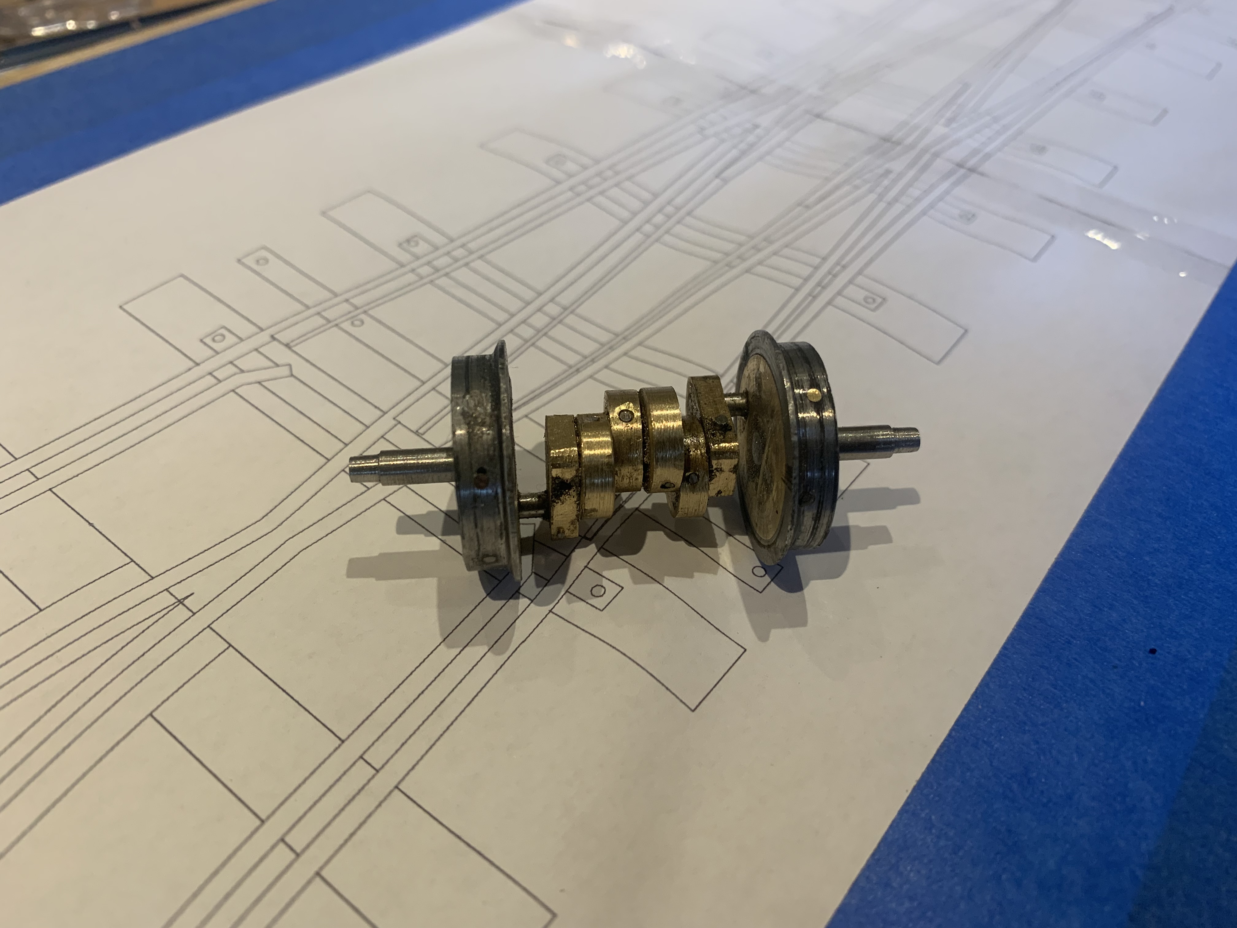
I have been using taper pins for a while, having a taper reamer to match the model engineering taper pins. These are a bit too big to be of use here, but I have found clock makers taper pins - which are available in a range of small sizes. The axle in the photo above was secured using such pins, but putting the pins through the face of the eccentric wasn't really satisfactory. In fact I made the whole axle yet again. This time I put a taper pin in from the side through 2 eccentrics and one crank - then the same on the other side. When it came to fixing the axles the crank pins to the wheels and cranks I put one long taper pin in through the wheel tread, down through the crank pin and into the axle. My third attempt seems to work!
I was finding it difficult to set the valve timing when I first worked on this. It involved removing one cylinder so that I could set the other valve, putting it back and removing the other to repeat the operation. Not exactly satisfactory. So I opened up the front of the valve chamber so that I would be able to see the valves opening (using a torch). Still quite bit of dismantling to adjust the valve. Because the cylinders are mounted on the boiler, the boiler and cylinder block come off as a unit, so everything has to be taken apart to adjust the valves. I got quite close and then realised that there was another way. Not exactly conventional, but workable. The eccentric strap is attached to its rod by a 10BA thread, and the rod attaches to the expansion link with the same thread. So by taking one eccentric strap off the eccentric, I could just get it clear of the mechanism, to unwind it or wind it by half a turn and then reassemble and try the timing again. Since one eccentric controls one cylinder on forward, and another eccentric controls that cylinder in reverse, that meant adjusting 4 straps individually.
I think the video which I used in the first post demonstrates that it worked!
You can see from the photos in the first post that the boiler follows the real practice - in that it has a smokebox with a hinged lid, the double safety valves on a block to one side, There are 4 boiler tubes in the boiler, rather than the single tube in "Idris". The regulator is largely hidden inside the smokebox. It is to have a ceramic burner and gas tank, in the bunker. The water tank is made, and holds water, I hope to be able to add a crank driven water pump in due course.
I am now working on the bunker and the gas tank.
Trevor
To get the Stephenson valve timing correct I made a jig to set the eccentrics onto the axle. It consists of a block of brass with a hole in it. The distance between the hole and the edge is slightly less than the radius of the eccentrics, so that when assembled the valve will open just after the piston reaches the end of its travel. So the jig sets the 2 eccentrics on the axle, offset not 180 degrees apart, but about 170 degrees apart. Using the jig, the lathe carriage and a set square the two sets of eccentrics are set 90 degrees from each other, and as in this photo :
In a similar way the crank can be set at 90 degrees to the eccentrics.
This is the axle assembled:
I have been using taper pins for a while, having a taper reamer to match the model engineering taper pins. These are a bit too big to be of use here, but I have found clock makers taper pins - which are available in a range of small sizes. The axle in the photo above was secured using such pins, but putting the pins through the face of the eccentric wasn't really satisfactory. In fact I made the whole axle yet again. This time I put a taper pin in from the side through 2 eccentrics and one crank - then the same on the other side. When it came to fixing the axles the crank pins to the wheels and cranks I put one long taper pin in through the wheel tread, down through the crank pin and into the axle. My third attempt seems to work!
I was finding it difficult to set the valve timing when I first worked on this. It involved removing one cylinder so that I could set the other valve, putting it back and removing the other to repeat the operation. Not exactly satisfactory. So I opened up the front of the valve chamber so that I would be able to see the valves opening (using a torch). Still quite bit of dismantling to adjust the valve. Because the cylinders are mounted on the boiler, the boiler and cylinder block come off as a unit, so everything has to be taken apart to adjust the valves. I got quite close and then realised that there was another way. Not exactly conventional, but workable. The eccentric strap is attached to its rod by a 10BA thread, and the rod attaches to the expansion link with the same thread. So by taking one eccentric strap off the eccentric, I could just get it clear of the mechanism, to unwind it or wind it by half a turn and then reassemble and try the timing again. Since one eccentric controls one cylinder on forward, and another eccentric controls that cylinder in reverse, that meant adjusting 4 straps individually.
I think the video which I used in the first post demonstrates that it worked!
You can see from the photos in the first post that the boiler follows the real practice - in that it has a smokebox with a hinged lid, the double safety valves on a block to one side, There are 4 boiler tubes in the boiler, rather than the single tube in "Idris". The regulator is largely hidden inside the smokebox. It is to have a ceramic burner and gas tank, in the bunker. The water tank is made, and holds water, I hope to be able to add a crank driven water pump in due course.
I am now working on the bunker and the gas tank.
Trevor
- dudeface
- Fireman

- Posts: 402
- Joined: Tue Nov 14, 2023 3:35 am
- Location: Southern Wisconsin
- Contact:
Re: George Henry
Nice chunky little loco 
- Old Man Aaron
- Driver

- Posts: 1185
- Joined: Wed Oct 19, 2016 11:08 am
- Location: Sunshine Coast QLD, Australia
-
Trevor Thompson
- Driver

- Posts: 1190
- Joined: Fri Oct 05, 2018 6:30 pm
- Location: South West Wales
Re: George Henry
The gas tank started life as a length of brass square section, to which a brass lid and bottom were added. When I drilled the holes for the gas valve and the gas control valve, there didn't seem to be much space left for the gas, so I added a square section to the side, to fill the space between the frames under the bunker. The gas tank and the basic components for the gas valve:
The gas valve passes all of the way through the tank, with the gas taken from the top, and passing down the middle of the valve body to exit under the tank ready to attach a copper pipe for the burner. The valve body and filler bush silver soldered into place:
and from underneath:
In both of the above photos you can also see that the base of the bunker has been silver soldered into place. Having checked that it holds water, and pressure, that is the last time it will be silver soldered. So it is ready to have the bunker soft soldered to the base.
Trevor
The gas valve passes all of the way through the tank, with the gas taken from the top, and passing down the middle of the valve body to exit under the tank ready to attach a copper pipe for the burner. The valve body and filler bush silver soldered into place:
and from underneath:
In both of the above photos you can also see that the base of the bunker has been silver soldered into place. Having checked that it holds water, and pressure, that is the last time it will be silver soldered. So it is ready to have the bunker soft soldered to the base.
Trevor
-
Trevor Thompson
- Driver

- Posts: 1190
- Joined: Fri Oct 05, 2018 6:30 pm
- Location: South West Wales
Re: George Henry
I now have the bunker and tank assembled and fitted to the frames, temporarily. I will fit brackets to the sides later to match the brackets which hold the water tank in place.
I have recently discovered polishing "mops" for the Dremel, and they made it really easy to polish the tapered point on the gas valve. It sealed really well first time!
Back to finding all the leaks around the boiler fittings before going on with the burner.
Trevor
I have recently discovered polishing "mops" for the Dremel, and they made it really easy to polish the tapered point on the gas valve. It sealed really well first time!
Back to finding all the leaks around the boiler fittings before going on with the burner.
Trevor
- Old Man Aaron
- Driver

- Posts: 1185
- Joined: Wed Oct 19, 2016 11:08 am
- Location: Sunshine Coast QLD, Australia
Re: George Henry
That's a really tidy valve arrangement, Trevor.
The Dremel is my favourite modelling tool, bar none.
Regards,
Aaron - Scum Class Works
- RlwPowell
- New User

- Posts: 2
- Joined: Thu Aug 06, 2026 7:16 pm
- Location: Kenilworth
Re: George Henry
Do you draw up/calculate the valve gear, Trevor?
I have been playing with this for a DeWinton using Don Ashton's book on Stephensons*, I usually end up with tiny eccentrics - much the same as the full size locos
Richard
*The gear I worked out for a 3 1/2" gauge loco works fine
I have been playing with this for a DeWinton using Don Ashton's book on Stephensons*, I usually end up with tiny eccentrics - much the same as the full size locos
Richard
*The gear I worked out for a 3 1/2" gauge loco works fine
Who is online
Users browsing this forum: No registered users and 16 guests