Made the running chassis for the Bagnall project today! Frames cut, chassis spacers machined and tapped and the whole shaboodle assembled with the cylinders, wheelsets and reverser from the Locobox.
It's looking great and proportions certainly fit the look of the bagnall much more than the original Locobox!
Next step is to machine the bufferbeams and smokebox apron.
Pictures to follow!
Locobox Loco on Ebay - Rebuild in Progress
-
Rob
-
andysleigh

- Driver

- Posts: 1362
- Joined: Thu Oct 18, 2007 6:21 pm
- Location: Guildford
- Contact:
That not hackworth. Thats bagnall price valve gear.Rob wrote:because thats what bagnall loco's had, atleast this one:
http://www.davewatkins.pwp.blueyonder.c ... Afront.jpg
http://www.davewatkins.pwp.blueyonder.c ... GAside.jpg
The only bagnall i know of to have hackworth is the MJ engineering 7 1/4" gauge bagnall
-
alan2525
-
alan2525
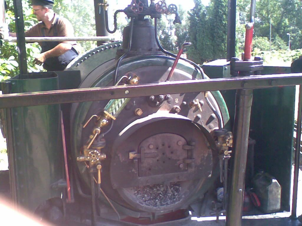
Rob, could you get a photo of where the pipework at the front of the saddletank at the bottom, it links the two sides of the tanks together and I can't work out where it's supposed to run too?Rob wrote:looking good alan. i can get some more pics on moday if you need them of leonard, just ask which bits.
yes jim they are the injectors. one either side of the firebox and its a blowdown on the bottom of the gauge glass. im pretty sure the clack is in the injector like billy said.
-
MTA
If memory serves me right then it only links either side of the tanks, Alan.alan2525 wrote:Rob, could you get a photo of where the pipework at the front of the saddletank at the bottom, it links the two sides of the tanks together and I can't work out where it's supposed to run too?Rob wrote:looking good alan. i can get some more pics on moday if you need them of leonard, just ask which bits.
yes jim they are the injectors. one either side of the firebox and its a blowdown on the bottom of the gauge glass. im pretty sure the clack is in the injector like billy said.
I can't recall if it links to anything...
-
SillyBilly
-
alan2525
Thanks, learning the correct terminology too now!SillyBilly wrote:The balance pipe I suppose might have a valve on it for draining the tank, but I can't see it likely otherwise.

I've done a bit more work on the loco today and it's slowly becoming more loco-like! I've removed a lot of the paper templates and replaced with brass!
It's certainly come a long way since this:

It now looks like this:



-
Rob
im loving that alan.
as for the pipework linking the tank,
it just goes from one side to the other to balance the water level, and as will said, there is a bung at the bottom to drain the tank.
you can just about see the threaded brass bung behind the exhaust pipe
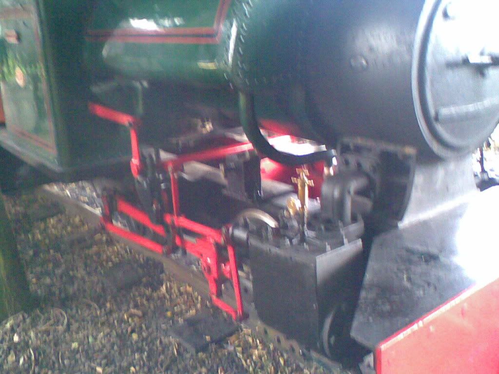
if you need any more pics, let me know on here by 2 oclock today and ill get em for tonite, or im going down on friday so can get some then. ill also get a pic of the "bagnall" makers plate if you want to make up some for it.
as for the pipework linking the tank,
it just goes from one side to the other to balance the water level, and as will said, there is a bung at the bottom to drain the tank.
you can just about see the threaded brass bung behind the exhaust pipe
if you need any more pics, let me know on here by 2 oclock today and ill get em for tonite, or im going down on friday so can get some then. ill also get a pic of the "bagnall" makers plate if you want to make up some for it.
-
alan2525
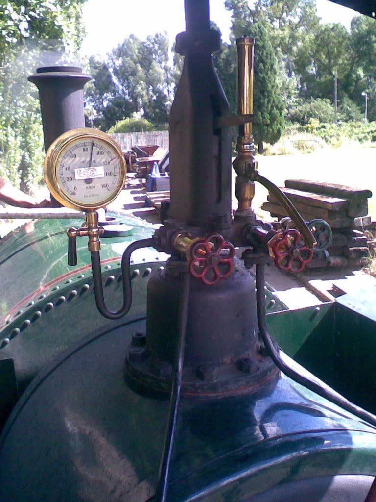
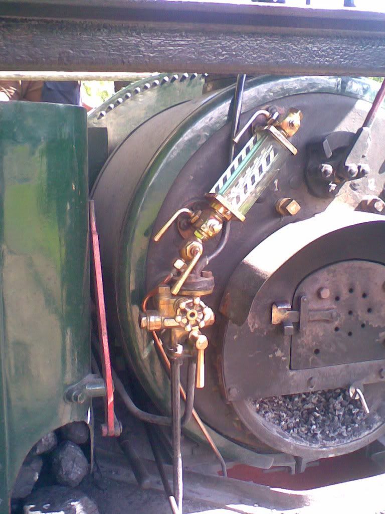
Thanks for the info Rob! Sounds like that pipework is a little simpler than I thought it was! Could you try to get some shots inside the cab, showing the coal bunker on the left hand side. Also the sanders mounted under the saddletank? Wendy doesn't have them but I'm going to pick and choose a few details to add some welcome detail!
I've had to rubber band some of the measurements on the loco to work around the current boiler, I wouldn't want the boiler any smaller for practicalities in 16mm. Most of the important proportions remain unchanged though!
Next step is cutting out the ends of the saddletank and silver soldering it together with a couple of lengths of brass tube, then the tricky bit of rolling the wrapper and bending the radius' on the bottom corners.
Cheers,
Alan
I've had to rubber band some of the measurements on the loco to work around the current boiler, I wouldn't want the boiler any smaller for practicalities in 16mm. Most of the important proportions remain unchanged though!
Next step is cutting out the ends of the saddletank and silver soldering it together with a couple of lengths of brass tube, then the tricky bit of rolling the wrapper and bending the radius' on the bottom corners.
Cheers,
Alan
-
made-in-england
- Trainee Driver

- Posts: 826
- Joined: Tue May 13, 2008 4:22 pm




-
alan2525
Frames and footplate are 1mm, sheetwork 0.7mm, buffer beams and tank ends are 1.6mm brass chassis spacers are 1/4" square bar.Rob wrote:what thickness and size brass are you using on the various parts alan?
A fair bit of progress, I've drawn up the cab parts, still need to refine some of the rivet detail prior to machining those bits. Rivet detail same on both sides, I need to add the row of rivets for the bunker on the left side of cab, I assume there's some sort of toolbox on the right?Rob wrote:any more progress?
I've also cut the ribs and tubes to construct the ends and spacers to solder up the saddletank, exact length of the tank will be established once the smokebox and cab are fitted to the loco.


Who is online
Users browsing this forum: 90733 and 43 guests