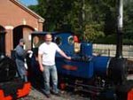
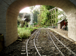
and the first one that I bought when the garden railway bug bit me.
But there have always been 5 little niggling things that I've never liked about it,
so now, I decided, is the time to address these problems.
First. The Radio Control:-
Mine was supplied with an ACOMS 2 channel 2.4GHz controller of the type used for
model cars, with a wheel for steering and a trigger for speed and direction. Roundhouse
had wired up the R/C in such a way that the steering wheel gave speed with forward / reverse
whilst pulling on the throttle trigger sounded the horn.
I have never liked this arrangement as I find it cumbersome to use, also I've found that
the ACMOS R/C is very limited in it's range so I decided to change it for a Planet 5
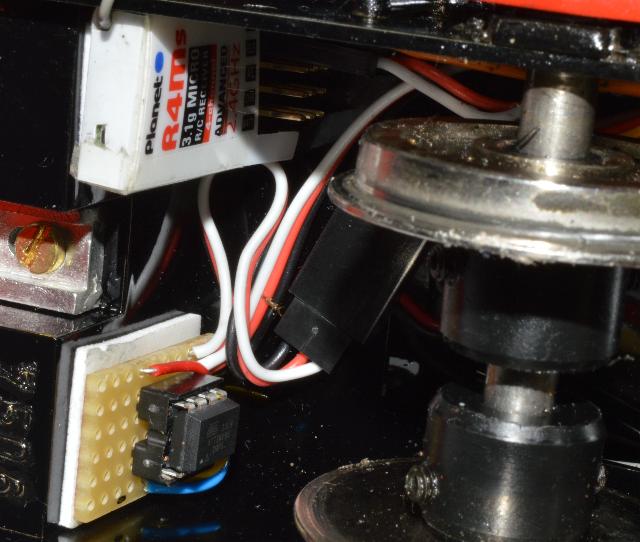
system with the miniature R4Ms receiver, this fits neatly into the same position as the
ACMOS receiver underneath the loco.
Second. The Driving Lights:-
I need to change the yellow LED front and rear driving lights for bright white LEDs
as I could never see the point of them being yellow in the first place.
If they're driving lights then surly they need to be as bright as possible.
This turned out to be a nice straightforward job to do as it was simply a
case of unsoldering the 4 old LEDs from their mounting strips and soldering
in the new ones.
Third. The Side Lights:-
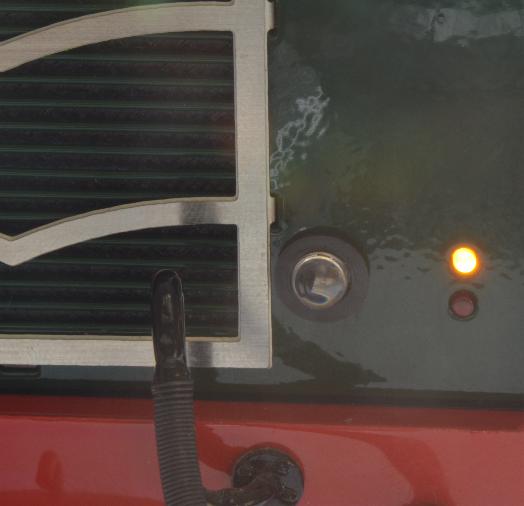
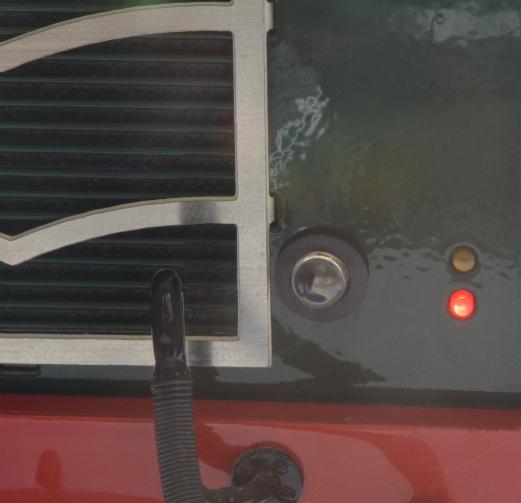
These are 4 LEDs, 2 front and 2 rear, one red and one yellow at each end and these are
always on, it doesn't make sense to me to always show red and yellow, surely it should be yellow
at the front and red at the rear changing colour when the direction of travel is reversed.
The polarity of the LEDs is not correct for what I need to do so I need to reverse the polarity
of the red LED on the front of the loco and the Yellow LED at the rear.
It was at this point that I discovered that Roundhouse had glued them into the mounting brackets
on the bodywork so there was no other alternative other than breaking them out and fitting new ones.
With the LEDs now wired correctly I needed some way of driving them.
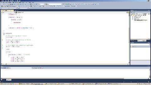
For me, the easiest way to do this is with a micro controller and a bit of C code to intercept the direction
data from the R/C receiver and to drive the LEDs accordingly.
I fitted the micro controller along side the R/C receiver underneath the chassis with the chip
easily accessible if I need to play around with the code in the future.
Fourth. The Sound:-
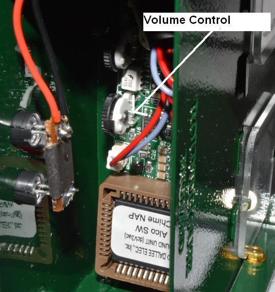
It’s far too loud, there is a switch for turning the sound off but on removing the bodywork
and examining the sound module, I discovered that there was a volume control fitted to it,
so this turned out to be an easy one to fix.
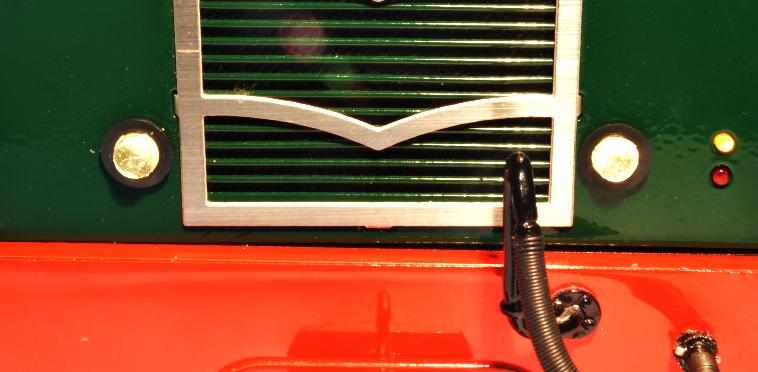
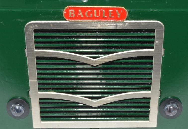
Fifth. The Radiator Grill:-
You can see the loud speaker for the sound module through it and it looks awful, so some sort
of internal cover was needed.
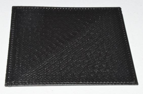
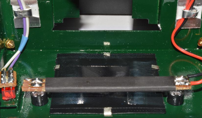
After an unsuccessful search around for a bit of thin black plastic I decided to custom
make one on the 3D printer out of black ABS and thin enough to be held in place by
the tabs of the radiator grill where they poke through the bodywork.
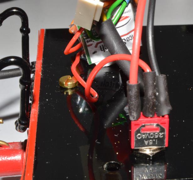
Then one final thing, which I wasn’t planning on doing, is when looking at the data sheet
for the sound module, I noticed that it had a bell as well as a horn. It only took a bit of wire
and a switch (the hole for the switch is already there) and now I can change between the two.
So that’s it, job done and now I have a Criccieth Castle which I’m really happy with rather than one
which was just OK.