Page 1 of 1
Shunter for the RWLR
Posted: Fri Nov 01, 2013 7:44 pm
by tom_tom_go
Some of you may of seen that I recently bought this off eBay:
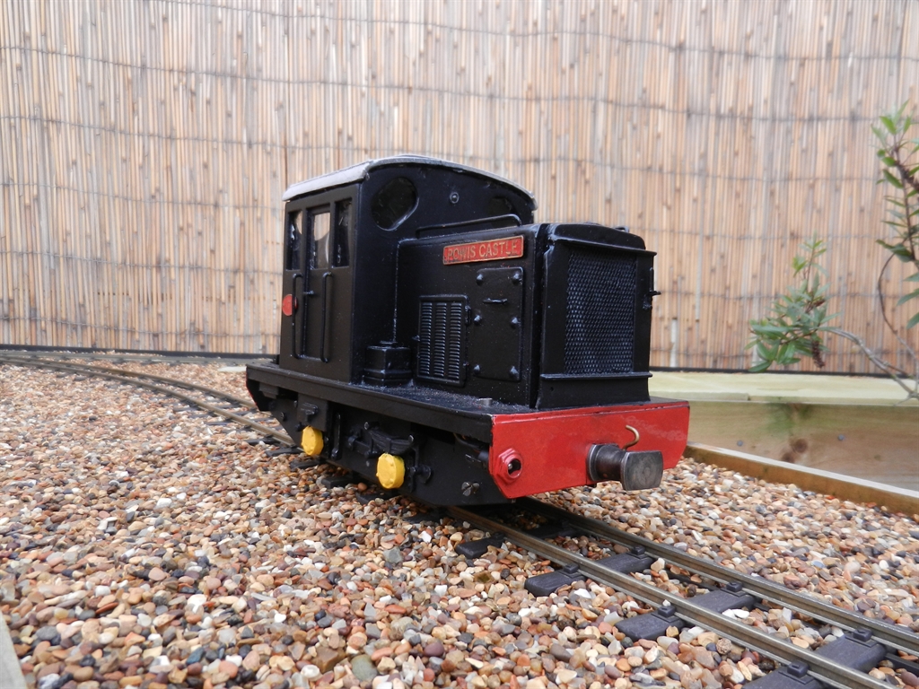
It's a bit tired, however, runs well as it has a Brian Jones Mac5 unit installed.
I like watching the running gear on locos so decided the first thing to go were the fake side panels:

Plenty of cosmetic changes to do although I could not resist buying a sound unit for it (click below to hear):
http://www.mtroniks.net/resources/DieselCanalBoat.MP3
Posted: Fri Nov 01, 2013 8:45 pm
by steamie1
Looks great. I have built one similar which comes out in Gardenrail 232.
Posted: Sat Nov 02, 2013 12:54 am
by Big Al
Nice sound on the audio card Tom,
Posted: Sun Nov 03, 2013 2:12 pm
by DVT Dweller
Those sound cards sound really good. Does the engine sound speed increase with the motor speed. Also how does it connect with the the RC? I couldn't work it out from the instructions on the web site.
Posted: Sun Nov 03, 2013 4:18 pm
by Big Al
As shown below the Blue and Yellow wires come from the motor and when the power to the motor increases the sound changes that's the theory anyway. Click below.
http://www.mtroniks.net/resources/digiS ... nual_4.jpg
Get one of these radio switches and plug one end into the radio control receiver on a spare channel I used the left/right on the left hand stick . Left starts the engine and tick over Left again stops engine sound. Right sounds the Horn. The two Gray wires that are shown going to the battery go into the plug on the other end of the radio switch and gets it power through the radio receiver so do not go to the battery as shown in drawing above. click below.
http://www.mtroniks.net/details1.asp/Pr ... itcher.htm
Hope this makes sense if not just ask.
Posted: Tue Nov 05, 2013 11:01 am
by tom_tom_go
I just received my switcher and sound card today, however, it's max voltage appears to be 12v and the battery in my loco is 15v.
What battery are you using in your loco Al?
Posted: Tue Nov 05, 2013 11:54 am
by Big Al
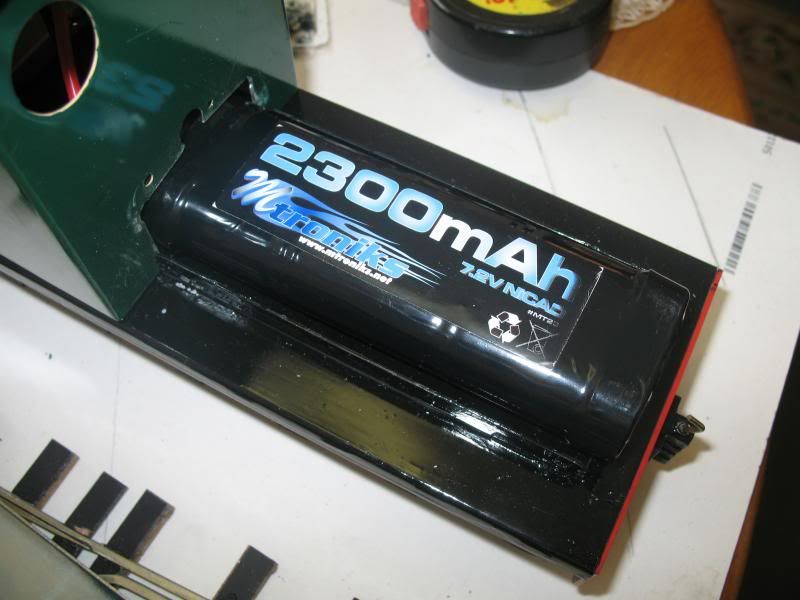
7.2v - 2300 m.amp - nicad radio control car battery.
Posted: Tue Nov 05, 2013 9:52 pm
by tom_tom_go
Thanks Al. I have had to order a 9.6v pack as the Mac5 speed controller installed in the loco needs a minimum of 9v
So do you connect the motor terminals from the sound unit to the speed controller or directly to the motor itself?
If you have any pictures or wiring diagram's that would be great!
I am also going to put in a 3A car fuse.
Posted: Tue Nov 05, 2013 10:56 pm
by Big Al
As I said above the Blue & Yellow wires go to the motor and the Gray wires go to the radio switch and the other lead R/Y/B from the radio switch plugs into loco receiver and not to the battery as it is powered from the receiver.
My speed controller is wired as shown below
http://www.chuffed2bits.com/ESC%20setup ... ctions.pdf
You can if you like have a 2 into 1 lead from the motor to the sound and speed controllers. Or connect it any ware on the motor lead wires I found it easiest to solder the blue & yellow leads to the motor terminals.
Posted: Wed Nov 06, 2013 12:15 pm
by tom_tom_go
Thanks for the help Al.
So this is how I think it should be wired:

Does the sound unit get it's power from the switcher then as this is the part I am unsure about.
Cheers,
Tom
Posted: Wed Nov 06, 2013 1:05 pm
by The Denying Dutchman
I like that, it has lots of character.
Posted: Wed Nov 06, 2013 2:33 pm
by Big Al
The black and red power wires from the sound card go Red to the fuse and the Black to the battery. The sound card must be connected via the on off switch as it will drain battery if left live as I found out with a flat battery. Triple check polarity as some of the transistors are not + _ reversible before you fire it up.


