I have successfully used .024 brass rod in my sight glasses.
Needed to cut the wire over length and bend small J shapes on each end to keep the wire centered and not laying against the side of the glass.
My Live Steam Loco's No.10 - Cheddar/GRS Steam Tram
-
Chris Cairns
- Driver

- Posts: 2372
- Joined: Mon Oct 29, 2007 7:25 pm
- Location: Glasgow, Scotland
This project had been on hold recently, primarily due to my volunteering with a Railway Group including footplate duties on steam days, trying to find a cost effective 2.4GHZ system to replace the factory supplied 27MHZ system which suffers from interference and a large aerial to take out your host's eyes!, and pondering how to resolve the gas burner bending the resin body.
So here is the radio control set-up I settled on.

All Cheddar oscillating models came with a standard size servo fitted (no manual control possible). So I've added a standard 4 x AA battery box with a JST/BEC (Battery Eliminator Circuit) connector (plugs straight into the receiver so no power switch required which alleviates any problems with failure of these generally cheap switches), a MLP4DSM 4 channel DSM 2 .4 GHz transmitter (£9.99 inc P&P) and a Orange RX R615 6 channel DSM2 2.4 GHz receiver (£7.80 inc P&P).
Before everyone rushes out and buys this transmitter/receiver combination please be aware that they come with no instructions and there are some important features that have previously been undocumented. I appreciate not everyone reads my comprehensive postings so I'll try to keep it brief but relevant (PM me if you would like more details).
Transmitter - It has a low voltage warning system (continuous beeps on powering up). Mode 2 configuration with servo reversal on elevator (right stick fore & aft), aileron (right stick left & right) & rudder (left stick left & right) channels but sadly not the throttle (left stick fore & aft). Dual Rate option controlled by pushing down on right stick with power on (Full rate indicated by steady power LED, low rate indicated by flashing power LED). Bind mode is entered by pushing & holding down the left stick before switching on the power. Only needs 4 x AA batteries for power. Weight including 4 x AA batteries - 0.29kgs.
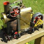
Receiver - Comes with a binding plug. Steady orange LED indicates it has bound with a steady signal, flashing orange LED indicates in Bind mode. An additional red LED indicate a loss of signal and the amount of flashes tells you how many times it was lost during operation. This model has been improved with fitting a second aerial - these need to be placed at 90 degrees to each other for best results so I've covered the aerials with some cable sheathing (black sheathing on top of the orange wire aerial as seen in the above photo) to hold them in position. It has a programmable failsafe system, as the default setting (throttle channel minimum setting) would cause a big problem in this Cheddar model as that would mean the actual regulator/reverser control would go to fully open - Not to be Recommended (I have successfully programmed mine so the throttle channel will go to mid position when the signal is lost, which means the Cheddar regulator/reverser control would also go to the mid [Off] position - Phew!).
Only problem with this set-up is the throttle channel control is in the wrong direction for this Cheddar/GRS tram, and with no option for servo reverse on the transmitter (I am aware you could get a reverse facility to plug into your servo lead) the only mechanical option would be to fit a Z bent control rod on the opposite side of the servo as the regulator/reverser valve is located off-centre under the chassis as seen below -

In my previous experience Z bent control rods can flex a fair bit so I've just accepted that I need to operate the transmitter throttle control in the reverse direction (down from centre for forward movement) but as it has a friction control I've managed to achieve some very slow running leaving the throttle stick set and just watching the tram slowly going round and round.
With the receiver housed in an accompanying box van there is no way to see its LED's whilst running. So I found a simple solution to checking the receiver battery pack voltage, and only £1:59 inc P&P!

These are actually designed for checking LiPo battery packs with a corresponding on-board low voltage audible alarm, but the JST/BEC connector fits OK so it displays the voltage.
I've worked out a solution to hopefully stop the gas burner bending the resin body due to heat, but will need some better lighting conditions to take some photos to illustrate the problem.
Chris Cairns.
PS - I recently obtained a used Accucraft Edrig which has been modified with servo control on the regulator & reverser. The above transmitter/receiver combination works very well (throttle control is in the correct direction - forward/up for open).
So here is the radio control set-up I settled on.
All Cheddar oscillating models came with a standard size servo fitted (no manual control possible). So I've added a standard 4 x AA battery box with a JST/BEC (Battery Eliminator Circuit) connector (plugs straight into the receiver so no power switch required which alleviates any problems with failure of these generally cheap switches), a MLP4DSM 4 channel DSM 2 .4 GHz transmitter (£9.99 inc P&P) and a Orange RX R615 6 channel DSM2 2.4 GHz receiver (£7.80 inc P&P).
Before everyone rushes out and buys this transmitter/receiver combination please be aware that they come with no instructions and there are some important features that have previously been undocumented. I appreciate not everyone reads my comprehensive postings so I'll try to keep it brief but relevant (PM me if you would like more details).
Transmitter - It has a low voltage warning system (continuous beeps on powering up). Mode 2 configuration with servo reversal on elevator (right stick fore & aft), aileron (right stick left & right) & rudder (left stick left & right) channels but sadly not the throttle (left stick fore & aft). Dual Rate option controlled by pushing down on right stick with power on (Full rate indicated by steady power LED, low rate indicated by flashing power LED). Bind mode is entered by pushing & holding down the left stick before switching on the power. Only needs 4 x AA batteries for power. Weight including 4 x AA batteries - 0.29kgs.
Receiver - Comes with a binding plug. Steady orange LED indicates it has bound with a steady signal, flashing orange LED indicates in Bind mode. An additional red LED indicate a loss of signal and the amount of flashes tells you how many times it was lost during operation. This model has been improved with fitting a second aerial - these need to be placed at 90 degrees to each other for best results so I've covered the aerials with some cable sheathing (black sheathing on top of the orange wire aerial as seen in the above photo) to hold them in position. It has a programmable failsafe system, as the default setting (throttle channel minimum setting) would cause a big problem in this Cheddar model as that would mean the actual regulator/reverser control would go to fully open - Not to be Recommended (I have successfully programmed mine so the throttle channel will go to mid position when the signal is lost, which means the Cheddar regulator/reverser control would also go to the mid [Off] position - Phew!).
Only problem with this set-up is the throttle channel control is in the wrong direction for this Cheddar/GRS tram, and with no option for servo reverse on the transmitter (I am aware you could get a reverse facility to plug into your servo lead) the only mechanical option would be to fit a Z bent control rod on the opposite side of the servo as the regulator/reverser valve is located off-centre under the chassis as seen below -
In my previous experience Z bent control rods can flex a fair bit so I've just accepted that I need to operate the transmitter throttle control in the reverse direction (down from centre for forward movement) but as it has a friction control I've managed to achieve some very slow running leaving the throttle stick set and just watching the tram slowly going round and round.
With the receiver housed in an accompanying box van there is no way to see its LED's whilst running. So I found a simple solution to checking the receiver battery pack voltage, and only £1:59 inc P&P!
These are actually designed for checking LiPo battery packs with a corresponding on-board low voltage audible alarm, but the JST/BEC connector fits OK so it displays the voltage.
I've worked out a solution to hopefully stop the gas burner bending the resin body due to heat, but will need some better lighting conditions to take some photos to illustrate the problem.
Chris Cairns.
PS - I recently obtained a used Accucraft Edrig which has been modified with servo control on the regulator & reverser. The above transmitter/receiver combination works very well (throttle control is in the correct direction - forward/up for open).
-
Chris Cairns
- Driver
- Posts: 2372
- Joined: Mon Oct 29, 2007 7:25 pm
- Location: Glasgow, Scotland
Graeme is correct for this particular model. I found that the flue tube burner sits proud on the flue by some 2mm or so.GTB wrote:The body is a little too short to fit over the mechanism and has been forced on.
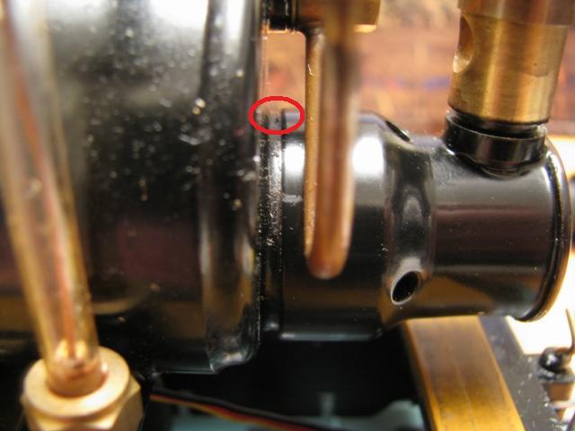
So the plan was to trim the end off the flue tube after I had completed the radio control upgrade.
However I had this niggling feeling that something was not right only with my model as Cheddar Models had a very good reputation for build quality and would not have sold a kit that was not fit for the purpose. This feeling was backed up by no mention of a problem with the resin body in Tag Gorton's review of this Cheddar/GRS tram in Garden Rail, and similarly a listing for a completed 32mm tram auction on-line (not eBay) stated that the resin body had not been affected by the heat.
Whilst doing some follow up into the 'howling' burner that was fitted to this tram (a phenomenon I'm aware of but have never experienced on my other Cheddar Models boilers) I discovered that there is a slight variation in these burners and fitting the burner from another boiler has put the burner closer to the boiler and thus opened up the gap to the resin body.

So with moving the boiler slightly on its mounts, making sure the gas tank sits up against the end of the boiler at the other end, and filing a small amount off the end of the flue tube there should be plenty of space for the resin body to fit properly. As it is just a loose fit on top of the skirt a couple of stops added to the cab floor should help position the resin body in the right place.
A fellow Forum member has pointed out the availability of cheap servo signal reverser's so I'll probably order one of those after the festive holidays and standardise which way the throttle channel controls the regulator.
Chris Cairns.
-
Dr. Bond of the DVLR

- Retired Director

- Posts: 4533
- Joined: Tue Jun 09, 2009 9:43 pm
- Location: Suffolk
- Contact:

Who is online
Users browsing this forum: No registered users and 37 guests