A place for discussing battery-electric locomotives, whether they're diesel, steam or even electric outline
-
LnBmad
Post
by LnBmad » Sat Jun 08, 2013 3:33 pm
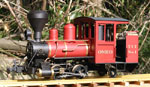
So this arrived for me this morning!

I have already removed the bodywork, regauged the pony and trailing trucks and made space ready for the radio gear and 2 battery packs.
I now need to work out how I adjust the centre driving wheels as it has the usual bachmann driving brick that's wider than 32mm on its own!
-
AndrewGVT
- Cleaner

- Posts: 54
- Joined: Tue May 21, 2013 7:45 pm
- Location: Hampshire
-
Contact:
Post
by AndrewGVT » Sat Jun 08, 2013 7:17 pm
Hi
I have been hoping you would do a post about this!

I noticed that the name plate is missing is it missing on both sides or just the one? I'm a asking because my one is missing one name plate. If so I buy a set (if I can find were to get them from) I could post the other to you if you want.
Great project, I will watch with interest.
Andrew
=============
Proper engineering techniques; use a hammer, if that fails, get a bigger hammer.
-
LnBmad
Post
by LnBmad » Sat Jun 08, 2013 10:46 pm
I have both plates. They were never fitted to the loco when originally purchased.
Think it will be a case of building a new motor mount and new axles.
-
LnBmad
Post
by LnBmad » Mon Jun 10, 2013 7:44 pm
Mini update:
I have been sent copies of the articles regarding changing the gauge on this loco...
I have also been sent some photos of a converted bachmann chassis using original parts...
Now it's time to cut the existing chassis up I think.... If it goes wrong ill just have to make a new one anyway
-
Peter L
Post
by Peter L » Fri Jun 14, 2013 6:35 pm
Following this with considerable interest!
-
LnBmad
Post
by LnBmad » Fri Jun 14, 2013 8:46 pm
So, a little further with this (although its been more planning that anything else)...
The centre driving wheels each separate from the driving gear via push fit. I will refit the wheels in the same manner, waning I have to reduce the axel on each wheel by 6.5mm. These will then fit in a chassis made of 0.8mm brass with 4 spacers in it (2 for the ends, 2 as motor mounts).
-
GTB
- Driver

- Posts: 1717
- Joined: Sat Mar 05, 2011 2:46 pm
- Location: Australia
Post
by GTB » Sat Jun 15, 2013 9:55 am
LnBmad:84799 wrote:These will then fit in a chassis made of 0.8mm brass with 4 spacers in it (2 for the ends, 2 as motor mounts).
0.8mm is OK in OO/HO scale but far too thin and flexible for SM32.
I'd use at least 1/16" or 1.5mm in this scale. Baldwin would have made the bar frames on the real Lyn 3" thick as they have more daylight than steel.
Regards,
Graeme
-
LnBmad
Post
by LnBmad » Mon Jun 17, 2013 6:22 pm
A little more progress as the bachmann power brick was removed today to be taken into the works this evening....

-
LnBmad
Post
by LnBmad » Tue Jun 18, 2013 5:37 pm
So managed to grab an hour in the barley pit works today. The power 'brick' was dismantled and work began at the axels.

So far 1 axel is complete. The clearance on the motor is tiny but it is clear so as soon as I can return to the works the other axel will be worked upon. Still unsure as to how this new chassis will attach to the body yet but will overcome one challenge at a time.
-
AndrewGVT
- Cleaner
- Posts: 54
- Joined: Tue May 21, 2013 7:45 pm
- Location: Hampshire
-
Contact:
Post
by AndrewGVT » Tue Jun 18, 2013 11:26 pm
looking good!
Andrew
=============
Proper engineering techniques; use a hammer, if that fails, get a bigger hammer.
-
LnBmad
Post
by LnBmad » Mon Jun 24, 2013 2:23 pm
Who is online
Users browsing this forum: No registered users and 47 guests