tom_tom_go wrote: ↑Sun Dec 10, 2017 9:41 pm
I really don't know what you are up to here but I feel I want to understand so can you go over in these last couple of posts with maybe simple diagrams of what you are trying to achieve?
Sure, OK, it is a similar process to what I was doing on page one of this thread when I was making the frames , buffer beams and coupling rods. You start with a much bigger piece for ease of manufacture and accuracy with hold down points outside of the finished part or later the hold points might be in the part as one produces holes witch can used.
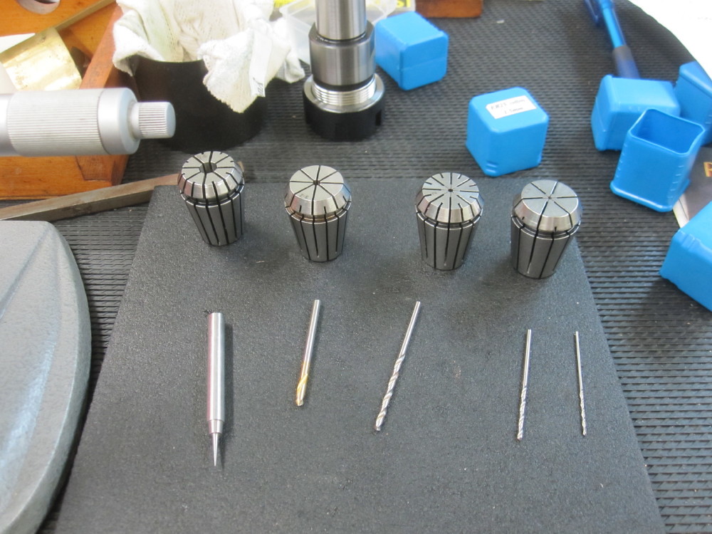
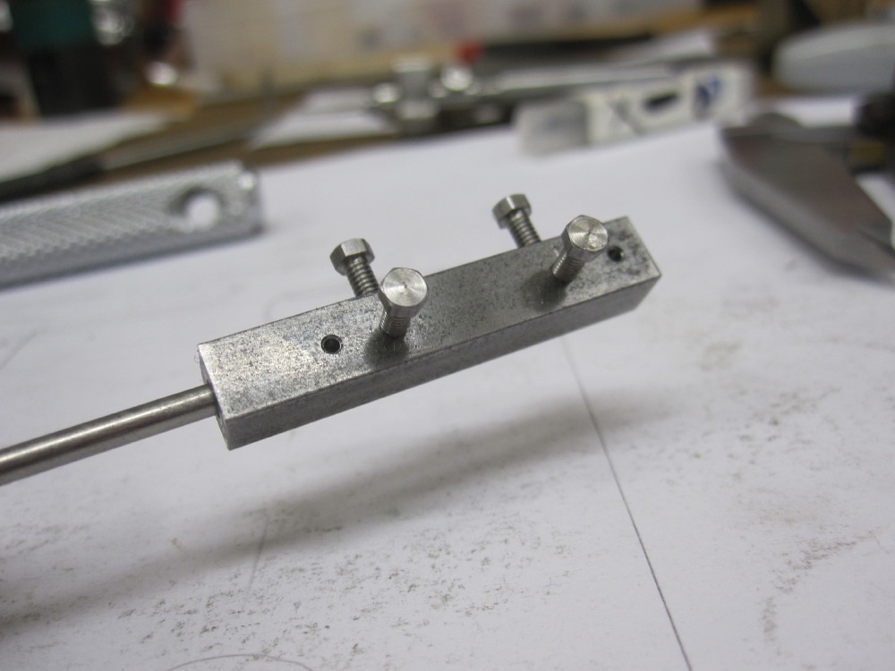
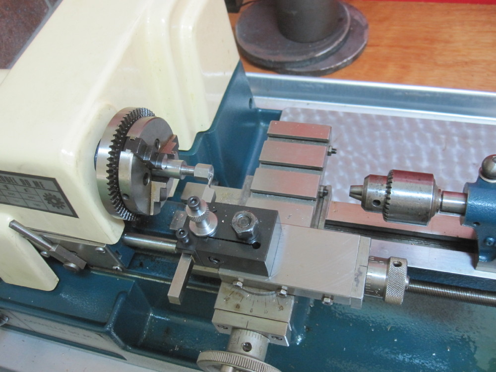
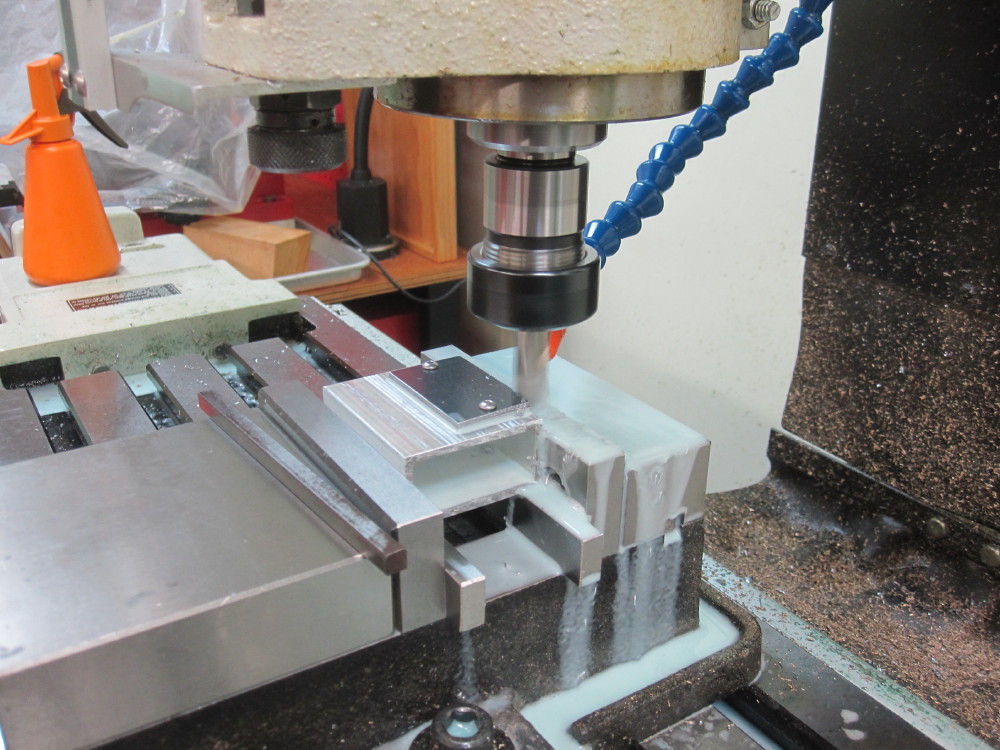
One starts with a holding block, for me it is suitable rectangle alloy channel section. I use alloy because it is to hand and left over from decades of projects and it easier on the tools than steel, especially with small drills. It does not have to have an accurate surface because I clamp it in the mill vice and give the top surface a pass with the mill cutter to give one a flat and true surface to start with. The idea is not not to disturb that hold down block in the vice till all is done or critical operations are completed where ever possible. The two pieces of stock steel, let us say the motion brackets roughs for the job are rough cut bigger than the finished part are then drilled in the excess material at each end and then held to the block in the vice with M5 screws or what ever, one can get at the nuts inside the alloy section for fitting, the two parts are done at the same time held together, in the main frame plates instance I used tool makers clamps which can get into the ends of the rectangular section and then get on with suitable drilling, then fitting M4 or M5 screws. In the motion bracket instance which I am working on I milled the edges to give me true four sides. The exact size does not matter. The true edges is what matters at the moment. The part is inside the perimeter of the material held down and between the two hold down screws
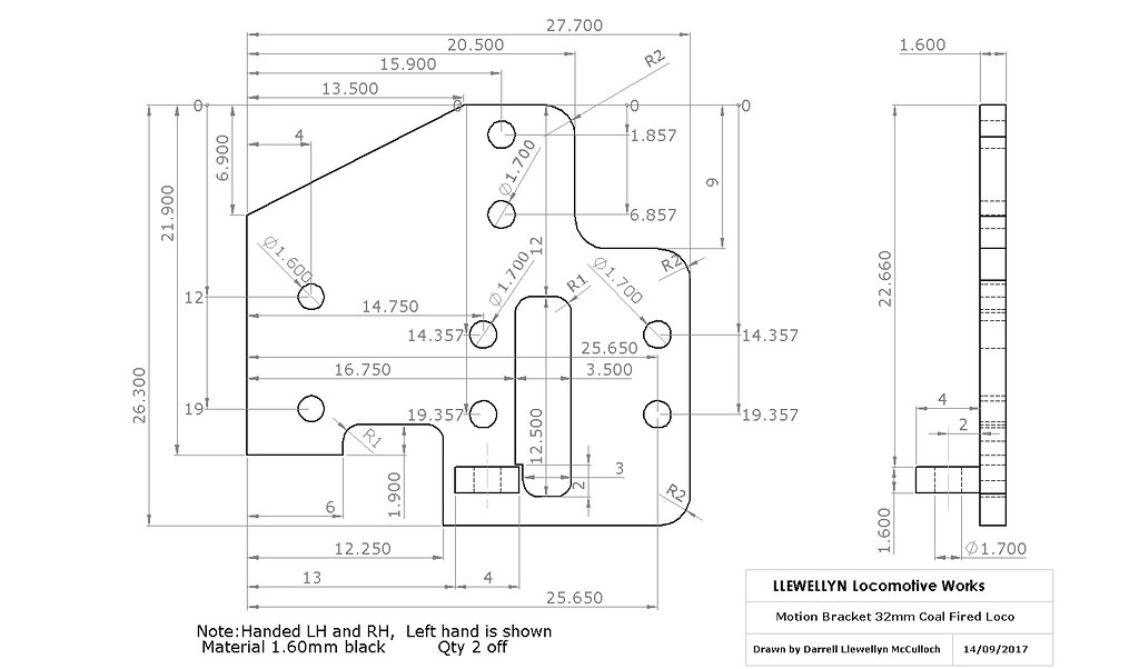
Note, the drawing has the dimensions from one of either two edges,
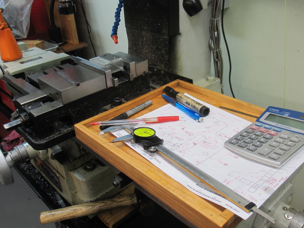
the "0-0" start point is the "origin" (top left hand corner of the part) and with the DRO (Digital Read Out) or when ever you mark out or use the feed dials on the mill you work from one edge. The same using your ruler to mark out the sanity checks or the using the digital readouts. (hand dials have back lash and you must work only in direction and that is errr yukk, with DRO you never get lost and it will beat the best hand dials every time)
The left hand edge of the drawing is the "0" for the X direction (mill table left to right)
I have the top edge of the motion bracket as "0" in the Y direction (mill table in and out)
One then uses a simple edge finder tool to find the two machined edges and then Zero the X and Y on the DRO. (allowing for half the diameter of the edge finder)
https://www.youtube.com/watch?v=5_qiPE5z7SE
That gives you the X = 0 (left to right datum point) and Y = 0 . In a minute you can get to .01mm location. One works from the edges where location accuracy is desired, such as a mounting face to another part. The motion bracket you want to be against the frame side and the top edge was chosen as the other datum edge.
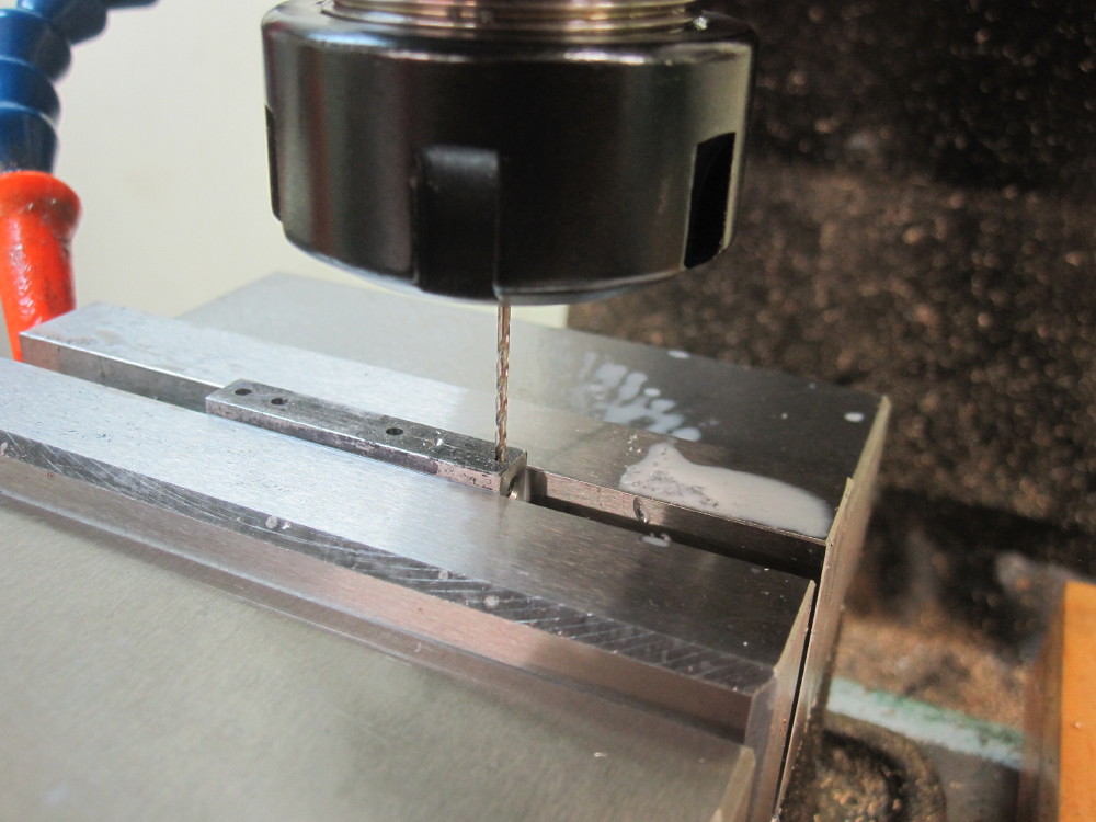
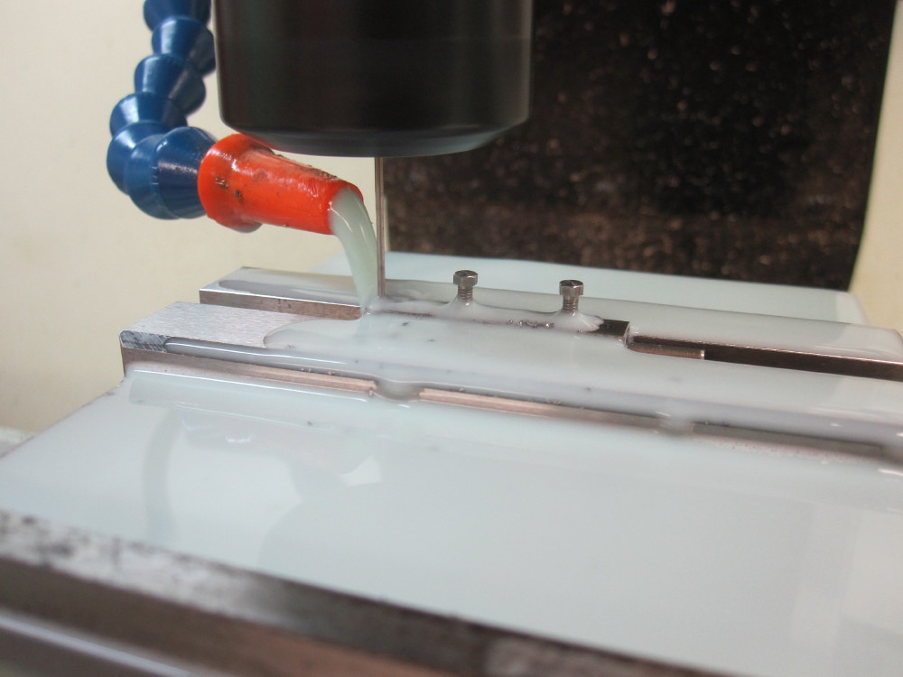
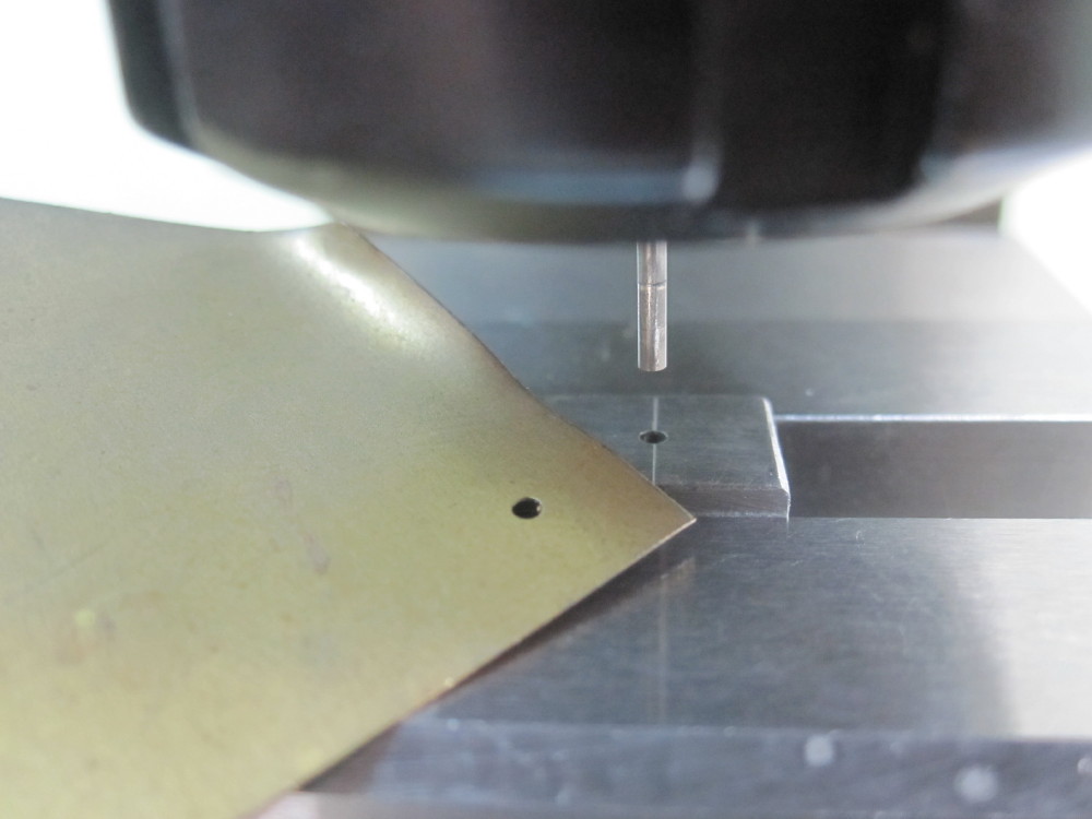
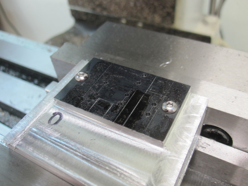
Then from there one drills as per the drawing. First I use a spotting drill to make the surface, going all over the place for all the holes using the DRO to locate accurately. With the DRO you can come back to the location with .005mm accuracy any time you wish.
Then one changes to the drill required and goes back to each hole and drills through, with suds to keep drill life long and a clean hole. Mark off the drawing in red pen the holes drilled with the correct size drill, one does not want too big of a hole in a location, too small can always be opened out. Sanity checks along the way.
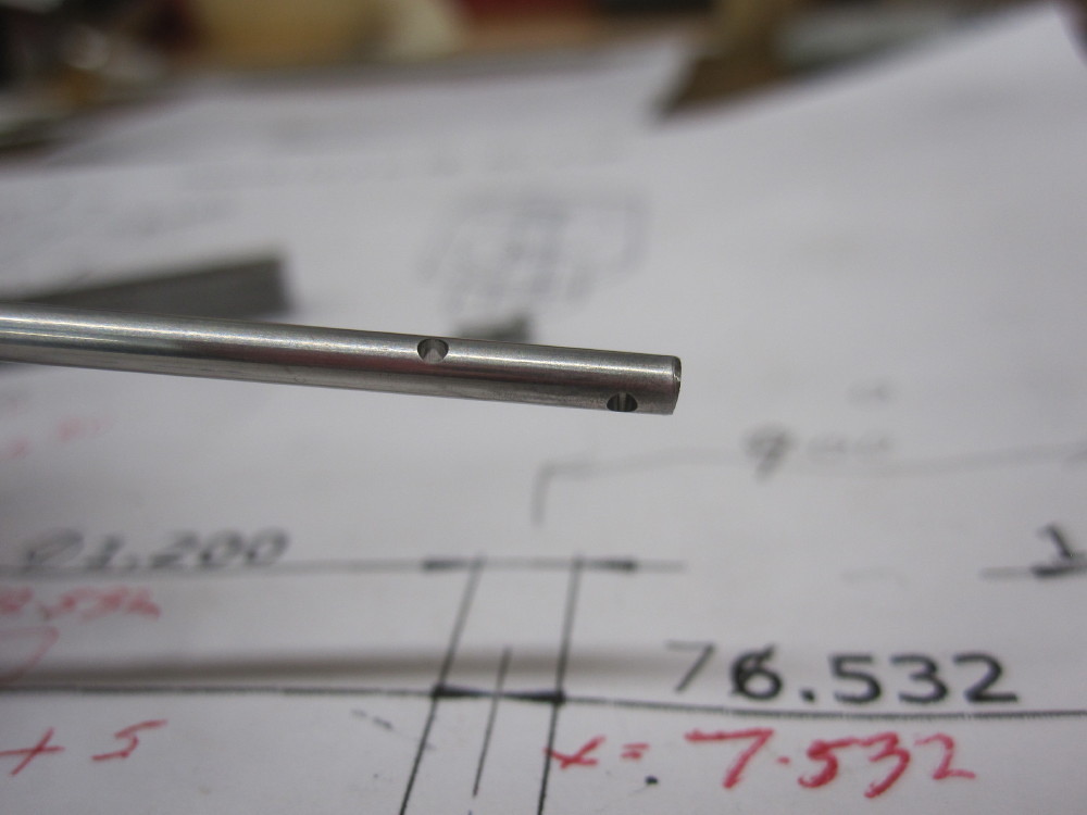
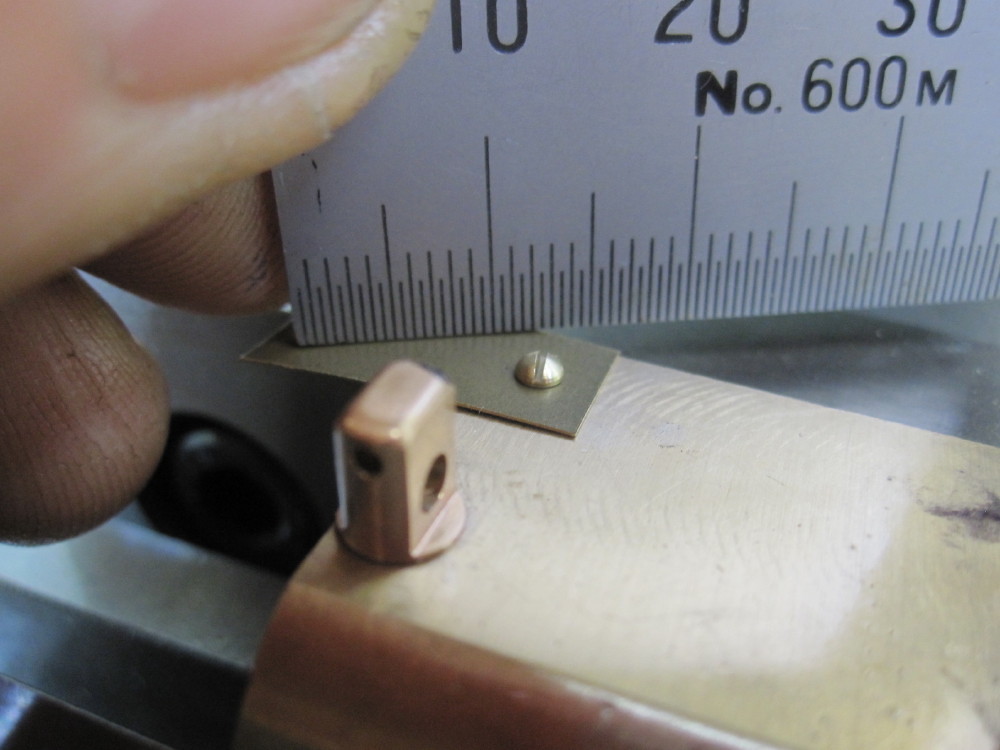
For example can you see the 1.60mm hole that is at location X - 4mm, Y-12mm It is for the mounting bracket angle of motion bracket to frame plate via a /16" rivet. That is a hole that is 4mm from the side edge that sits against the frame plate and it is 12mm from the top edge of the motion bracket. It has another hole directly below at X -4, Y-19 for the second rivet.
Later one cuts the excess material away and bingo. All this can be neater and more accurate than LASER cut material !
Most of us still mark out the locations with the scriber and or a vernier caliper with one edge sharp so the lines are a sanity check as one goes about the place drilling hols via the DRO, that helps to avoid mistakes or a miss read confusion. It still can occur ! and then you have a very accurate mistake. %#*!**!*74%55!!
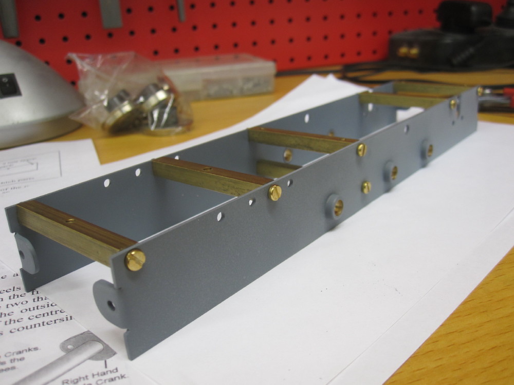
Later I will drill corners for slots for the radius rod to pass though and clearance for the connecting rod. The slide bar mounting bracket which is a little piece that is on the drawing but it is to be added later to the motion bracket plate but the hole is not on the attached drawing.
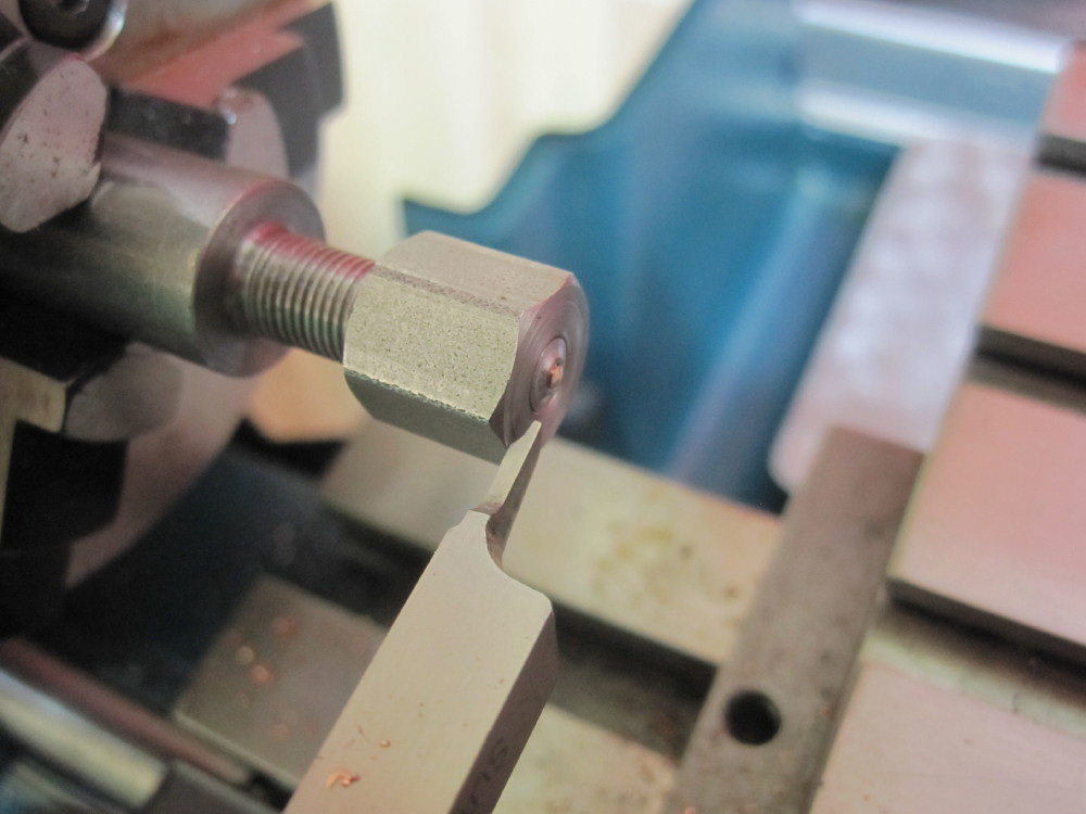
I will mill the slots and later complete the removal of the excess material around the parts, cutting off and milling/filing the edges. You can see on page one the buffer beams started much longer and then as I drilled I could use temporary bolts in the rivet holes and coupling hole to hold the plate and then Could cut off the excess which had the original hold down screws and clean the edges up neatly with a mill cutter.
The trick I am using with the DRO on the motion bracket is I have the origin +10mm away from the final edge of the motion bracket, so I can have the first hold down screws in this excess 10mm. Later I add hold down screws and will then cut and mill off the excess to the final lengths. It all sounds complicated but it is simple in reality.
Does that make sense?
I will try to do more pics of the process tonight and on-wards to explain easier.