IP Engineering Jessica build

Anything related to the garden railway world that is not catered for in another board
User avatar
-steves-
Administrator
Administrator
Posts: 2444
Joined: Thu Jul 28, 2011 1:50 pm
Location: Cambridge & Peterborough

IP Engineering Jessica build

Post by -steves- » Fri Nov 13, 2015 9:43 am

Well here are the first few pictures on my IP Engineering Jessica. These are rarer than the Jessie which is the 0-4-0 version of this much larger 0-6-0 kit. Most of the kit appears to be intact along with the detailing kit which is super hard to get hold of now.

I have already been in touch with a company and they are sending me the missing 6 wheels and a motor and gearbox. After that all I need is a bit of 1/8th rod to use as the one remaining missing axle. After that, I think its complete as best as I can tell. If anyone has a bit of 1/8th steel rod approximately 74mm long then please do get in touch and I will buy it from you as it saves me getting an entire length of it.

It did also have one missing axle bush, but I made one of these in a few minutes first thing this morning, fits perfectly, thank goodness ;)

If someone has some instructions they send give / loan / sell me for one of these I would highly appreciate it. None of it is properly bolted together or made to fit as yet, its just thrown together for the pictures ;)

Not sure if the entire build will be on here, but I will do my best to update here as I remember, failing that the build can be found here [/url]http://www.16mmforum.co.uk/viewtopic.ph ... 53#p53[url]

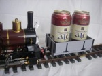
So, some basic pictures, pretty much as I took it out of the box.

Image

Image

Image

Image

Image
The buck stops here .......

Ditton Meadow Light Railway (DMLR)
Member of Peterborough and District Association
http://peterborough.16mm.org.uk/

User avatar
MDLR
Driver
Driver
Posts: 4027
Joined: Thu Jan 15, 2009 10:38 pm
Location: Near Ripley, Derbyshire, UK
Contact:

Post by MDLR » Fri Nov 13, 2015 12:24 pm

That'll keep you quiet for an hour and a half or so..............
Brian L Dominic
Managing Director
Flagg Fluorspar Co
www.mdlr.co.uk/ff.html

User avatar
Keith S
Driver
Driver
Posts: 1627
Joined: Thu Feb 24, 2011 11:44 pm
Location: Canada

Post by Keith S » Fri Nov 13, 2015 4:32 pm

Wow, it's all steel! It will be pretty heavy when it's finished, and indestructible!

Should be an impressive hauler when it's finished!

User avatar
-steves-
Administrator
Administrator
Posts: 2444
Joined: Thu Jul 28, 2011 1:50 pm
Location: Cambridge & Peterborough

Post by -steves- » Fri Nov 13, 2015 4:40 pm

Keith S:114232 wrote:Wow, it's all steel! It will be pretty heavy when it's finished, and indestructible!

Should be an impressive hauler when it's finished!
Its certainly a fair chunk of sheet steel and by the time you add in all that white metal and a battery, its going to do well to pull itself along, lol. As you say, it will certainly have some traction that's for sure ;)

Under the chassis there are a few more cross members of steel and the weight of those two white metal grills is quite impressive.

I certainly can't wait to see it done, though I have no idea what colour to do it as yet??
The buck stops here .......

Ditton Meadow Light Railway (DMLR)
Member of Peterborough and District Association
http://peterborough.16mm.org.uk/

Big Jim
Moderator
Moderator
Posts: 2694
Joined: Sat Jul 06, 2013 5:28 pm
Location: Near Llanelli

Post by Big Jim » Fri Nov 13, 2015 6:25 pm

I think I have a set of instructions, pm me with your address and I will stick em I the post for you.

User avatar
-steves-
Administrator
Administrator
Posts: 2444
Joined: Thu Jul 28, 2011 1:50 pm
Location: Cambridge & Peterborough

Post by -steves- » Fri Nov 13, 2015 9:36 pm

Big Jim:114236 wrote:I think I have a set of instructions, pm me with your address and I will stick em I the post for you.
Thanks Jim, someone is already posting me a set, but I really appreciate your kind offer. Its actually surprised me how many really nice people are still about.
The buck stops here .......

Ditton Meadow Light Railway (DMLR)
Member of Peterborough and District Association
http://peterborough.16mm.org.uk/

Big Jim
Moderator
Moderator
Posts: 2694
Joined: Sat Jul 06, 2013 5:28 pm
Location: Near Llanelli

Post by Big Jim » Sat Nov 14, 2015 10:42 am

I have to agree with you. It is always nice to be surprised by a kind action.
I have found that there are some very kind and generous people on this forum and various freebies have been sent and received over the years.

Lets keep it up folks!

Keep us all up to date with pictures of your build.
If at first you don't succeed, use a bigger hammer!

User avatar
-steves-
Administrator
Administrator
Posts: 2444
Joined: Thu Jul 28, 2011 1:50 pm
Location: Cambridge & Peterborough

Post by -steves- » Mon Nov 16, 2015 7:07 am

Big Jim:114245 wrote:I have to agree with you. It is always nice to be surprised by a kind action.
I have found that there are some very kind and generous people on this forum and various freebies have been sent and received over the years.

Lets keep it up folks!

Keep us all up to date with pictures of your build.
Many thanks for the instructions, they arrived on Saturday but I have not had chance to get on here since.

Did you want me to send them back to you once I am done, if so, just PM me your address.

Thanks again
Steve
The buck stops here .......

Ditton Meadow Light Railway (DMLR)
Member of Peterborough and District Association
http://peterborough.16mm.org.uk/

User avatar
-steves-
Administrator
Administrator
Posts: 2444
Joined: Thu Jul 28, 2011 1:50 pm
Location: Cambridge & Peterborough

Post by -steves- » Mon Nov 16, 2015 7:14 am

Slight update....

Unfortunately who ever started doing this kit decided that some of the holes in the fames weren't big enough and or they could not find any nuts to go on the M3 bolt, they then drilled out some of the holes to take a nut and bolt :oops: . For those that may not know, IP kits were designed to have the M3 machine bolts screwed into the holes to create their own thread on the way in, or a slightly better option, just use an M3 tap to get the thread in there. So, a few modifications now need to be done, particularly on the roof where I now either have to use an M3.5 or maybe even an M4 bolt and tap it out, or I have to suffer with nuts underneath the cab roof which to be honest, will be on show slightly, decisions, decisions.

If someone can think of a low profile way to do this I would be happy to hear it :D It does need to be removable though so spot welding or silver soldering it out, lol. :lol:
The buck stops here .......

Ditton Meadow Light Railway (DMLR)
Member of Peterborough and District Association
http://peterborough.16mm.org.uk/

User avatar
-steves-
Administrator
Administrator
Posts: 2444
Joined: Thu Jul 28, 2011 1:50 pm
Location: Cambridge & Peterborough

Post by -steves- » Mon Nov 16, 2015 8:39 am

A bit more of an update......

The motor and wheels arrived for this over the weekend too, which is great, but will involve some work to do.

The motor fits perfectly, as you would expect as its an IP Engineering Motor and gearbox.

The wheels however, I now have 6 flanged wheels which would give this long loco the turning circle of an AirBus! I need to remove the flanges from 2 of the wheels so they can go in the central position, I will also make the slightly smaller so they do not touch the track, but not too small that it will stand out like a sore thumb. The problem here is mounting the wheels in the lathe, as they have a have a very thin lip one side of them (I will post some pictures up when I get the chance to). My thoughts to overcome this is to put a bolt through the centre of the wheel, and use penny washers that do not touch the lip but fir inside the wheel, this should let me clamp down the bolt very tight so it does not spin when its in the lathe, or at least thats the plan.

If anyone has any better ideas to do this, then please post it up as I would be glad to hear it.
The buck stops here .......

Ditton Meadow Light Railway (DMLR)
Member of Peterborough and District Association
http://peterborough.16mm.org.uk/

User avatar
TonyW
Driver
Driver
Posts: 1357
Joined: Fri May 16, 2008 9:25 am
Location: North Wales
Contact:

Post by TonyW » Mon Nov 16, 2015 10:40 am

-steves-:114282 wrote:If someone can think of a low profile way to do this I would be happy to hear it
Fill the existing holes with soft solder, then drill and tap new ones in different places.
-steves-:114283 wrote:The wheels however, I now have 6 flanged wheels which would give this long loco the turning circle of an AirBus!
Are you sure you need to take off the flanges? I have a Lady Anne with six flanged wheels, and it seems quite happy on my 4ft 6in curves. It might be worth doing a test assembly to see what your loco does on your curves. And if it is tight then perhaps removing some material from the centre axle bearing thrust faces might just be enough to make it work.
Tony Willmore
Rhos Helyg Locomotive Works: http://www.rhoshelyg.me.uk
Facebook: https://www.facebook.com/RhosHelygLocoWorks

User avatar
-steves-
Administrator
Administrator
Posts: 2444
Joined: Thu Jul 28, 2011 1:50 pm
Location: Cambridge & Peterborough

Post by -steves- » Mon Nov 16, 2015 11:34 am

TonyW:114286 wrote:
-steves-:114282 wrote:If someone can think of a low profile way to do this I would be happy to hear it
Fill the existing holes with soft solder, then drill and tap new ones in different places.
-steves-:114283 wrote:The wheels however, I now have 6 flanged wheels which would give this long loco the turning circle of an AirBus!
Are you sure you need to take off the flanges? I have a Lady Anne with six flanged wheels, and it seems quite happy on my 4ft 6in curves. It might be worth doing a test assembly to see what your loco does on your curves. And if it is tight then perhaps removing some material from the centre axle bearing thrust faces might just be enough to make it work.
Will soft solder be ok to tap again? I would have thought it would pull straight through as its so soft, I have never tried, hence I am asking. Thoughts along that line, what about silver solder a small plate each hole, clean and wash thoroughly, then fill with soft solder and drill and re-tap, is that feasible and does it sound like it might work? I seem to recall an issue with silver solder and soft solder being in the same location?

Great idea on the centre wheels, would them being closer effect points though? Again, just thinking aloud here really? It does have a very long wheel base from front to back wheel, I have noticed that. I am unable to test it on my line as I don't have one as yet, I use a club one on a monthly basis, fortunately thats this Saturday, so I could take it there and try it then.
The buck stops here .......

Ditton Meadow Light Railway (DMLR)
Member of Peterborough and District Association
http://peterborough.16mm.org.uk/

User avatar
TonyW
Driver
Driver
Posts: 1357
Joined: Fri May 16, 2008 9:25 am
Location: North Wales
Contact:

Post by TonyW » Mon Nov 16, 2015 11:51 am

-steves-:114289 wrote:Will soft solder be ok to tap again?
No, you'd need to fill the holes and forget about them, then drill new holes in the steel alongside the filled holes.
Tony Willmore
Rhos Helyg Locomotive Works: http://www.rhoshelyg.me.uk
Facebook: https://www.facebook.com/RhosHelygLocoWorks

User avatar
-steves-
Administrator
Administrator
Posts: 2444
Joined: Thu Jul 28, 2011 1:50 pm
Location: Cambridge & Peterborough

Post by -steves- » Mon Nov 16, 2015 3:51 pm

TonyW:114290 wrote:
-steves-:114289 wrote:Will soft solder be ok to tap again?
No, you'd need to fill the holes and forget about them, then drill new holes  in the steel alongside the filled holes.
Ah ha, I see, yes, good idea, silly me :oops:
The buck stops here .......

Ditton Meadow Light Railway (DMLR)
Member of Peterborough and District Association
http://peterborough.16mm.org.uk/

Big Jim
Moderator
Moderator
Posts: 2694
Joined: Sat Jul 06, 2013 5:28 pm
Location: Near Llanelli

Post by Big Jim » Mon Nov 16, 2015 6:31 pm

What I did was open out the roof holes slightly and fitted counter sunk M3 set screws. I used epoxy to hold nuts in place on the flange on top of the cab sides as I was not overly convinced of the thread strength. The cab roof is covered by a sheet of plasticard held in place with smurf poo (blu tac) to cover the screws.
If at first you don't succeed, use a bigger hammer!

User avatar
MDLR
Driver
Driver
Posts: 4027
Joined: Thu Jan 15, 2009 10:38 pm
Location: Near Ripley, Derbyshire, UK
Contact:

Post by MDLR » Mon Nov 16, 2015 8:06 pm

Big Jim:114301 wrote:The cab roof is covered by a sheet of plasticard held in place with smurf poo (blu tac) to cover the screws.
I've never heard it called THAT before...................... :wav:
Brian L Dominic
Managing Director
Flagg Fluorspar Co
www.mdlr.co.uk/ff.html

User avatar
-steves-
Administrator
Administrator
Posts: 2444
Joined: Thu Jul 28, 2011 1:50 pm
Location: Cambridge & Peterborough

Post by -steves- » Mon Nov 16, 2015 9:14 pm

Big Jim:114301 wrote:What I did was open out the roof holes slightly and fitted counter sunk M3 set screws. I used epoxy to hold  nuts in place on the flange on top of the cab sides as I was not overly convinced of the thread strength. The cab roof is covered by a sheet of plasticard held in place with smurf poo (blu tac) to cover the screws.
I don't suppose you have any detailed pictures you could post up of the inside and outside to give me a better insight? Be great if you could :)
The buck stops here .......

Ditton Meadow Light Railway (DMLR)
Member of Peterborough and District Association
http://peterborough.16mm.org.uk/

Big Jim
Moderator
Moderator
Posts: 2694
Joined: Sat Jul 06, 2013 5:28 pm
Location: Near Llanelli

Post by Big Jim » Mon Nov 16, 2015 9:21 pm

ImageDSC_0028 by bigjimiflash, on Flickr[/img]

This shows the countersunk screws on the roof. Not exactly detailed but you get the general idea.

ImageDSC_0044 by bigjimiflash, on Flickr[/img]

This shows the plastic roof which has not been fitted properly at present, the thin plastic was taped around a large glass jar, which was filled with hot water and left to form its curve. Small strips of plastic will be stuck around the edge to fill the gap and when it is done properly it should be un-noticeable as it will only be 1mm thicker than a standard roof. If the C/S screws are still slightly proud they can be flattened off with a dremel type thing.

Sorry there are no more detailed pics at the moment but I will try and sort some the next time I am up the shed.

The whole build and all its trial and tribulations can be found here.
http://gardenrails.myfreeforum.org/ftopic9294-30.php
If at first you don't succeed, use a bigger hammer!

User avatar
-steves-
Administrator
Administrator
Posts: 2444
Joined: Thu Jul 28, 2011 1:50 pm
Location: Cambridge & Peterborough

Post by -steves- » Mon Nov 16, 2015 10:31 pm

Thanks for the pictures, very helpful.
I have to ask, but how did you do all those rivets?
I also quite like the rear grill filled in, food for thought :D
The buck stops here .......

Ditton Meadow Light Railway (DMLR)
Member of Peterborough and District Association
http://peterborough.16mm.org.uk/

Big Jim
Moderator
Moderator
Posts: 2694
Joined: Sat Jul 06, 2013 5:28 pm
Location: Near Llanelli

Post by Big Jim » Mon Nov 16, 2015 11:17 pm

The rear grill was filled in as there was no casting for it as the kit was second hand. The rivets are plastic ones from Cambrian models stuck on strips of plasticard.

Post Reply

Who is online

Users browsing this forum: No registered users and 7 guests