Tan-y-Bwlch Water Tower - Finished ( I think!)
Posted: Thu Dec 28, 2023 8:15 am
Ever since Trevor posted about his model of Tan-y-Bwlch water tower, several years ago, and then put his drawings into the Print Files section, I've had it in mind to build one for myself and I have looked at doing it a couple of times. The sticking point for me was that I don't have the 'stone' stencils that Trevor used for the stone tower and I didn't particularly want to buy any and the thought of creating all that stonework and printing it was equally daunting. However, a couple weeks ago I decided to bite the bullet and actually try.
I started with Trevor's flat blank panels for the stone work base but after importing the stl's in SketchUp, I modified the corners to a plain chamfer rather than his stepped joints because printing those and cleaning them up would be a pain. So I drew a slab of the correct plan dimensions and 4mm thick and then I drew horizontal guide lines at 6.5mm vertical spacing on one face.
Using the "freehand " drawing tool in SketchUp, I simply drew roughly equal shaped and sized 2D stones, in between the guide lines, taking care to get headers and stretchers at opposite ends of each row.
I then grouped this, duplicated the whole thing and placed the two units side by side. The LH one of the pair was then 'ungrouped' and the end stones on the RH side of it were adjusted to match the LH stones on the other unit. The grouped unit was then transferred to the other side and the LH side of the 'ungrouped' unit was again adjusted to match. Finally the ungrouped unit was re-grouped and the other unit discarded completely. The point of all this was to be able to print 4 identical units and the stonework continue round the corners and match.
The next step was to randomly pull up a selection of stones using the SU push-pull tool.
Then I selected the area between the stone faces ( the original flat slab face) and pushed that down 1mm, again using the push-pulltool, and I had a 3D stone wall face.
To complete the box I drew up a stepped top and bottom plate with stone indentations around the edges. The step fitting inside the box and giving something to hold everything square as it sets. These are identical since the bottom one will be more or less buried when out in the garden.
Once glued, I used some "Stonelux" Cotswold paint with fine sand mixed in to give a rough finish and then washed it with Citadel "Agrax Earthshade" to give a random effect.
Trevor has said that his model is based on the early version of the water tank. Not being a specific Ffestiniog modeller, I have only random pictures of the line and no good pictures of the water tank at any period. Looking online several pictures crop up showing the modern tank with pressed steel sides and twin discharge pipes, and there are a few which show partial side views of earlier tanks but with little detail. Now, in his stl zip file, Trevor has a water level gauge but no indication as to where it goes, and there is no detail of the discharge pipe, Oh, and shouldn't there be a ladder? Trevor does make mention of a supply feed pipe and one of the pictures that I found shows a pipe hooked over the back LH side of the tank, so far so good, but that picture also shows a vertical row of rivets on the tank side, not far from the back edge of the tank, which are not on Trevor's drawings. http://www.hall-royd-junction.co.uk/Rai ... _1966.html
So with the lack of any further information, I used Trevor's tank sides and printed them, intending to work out some details subsequently.
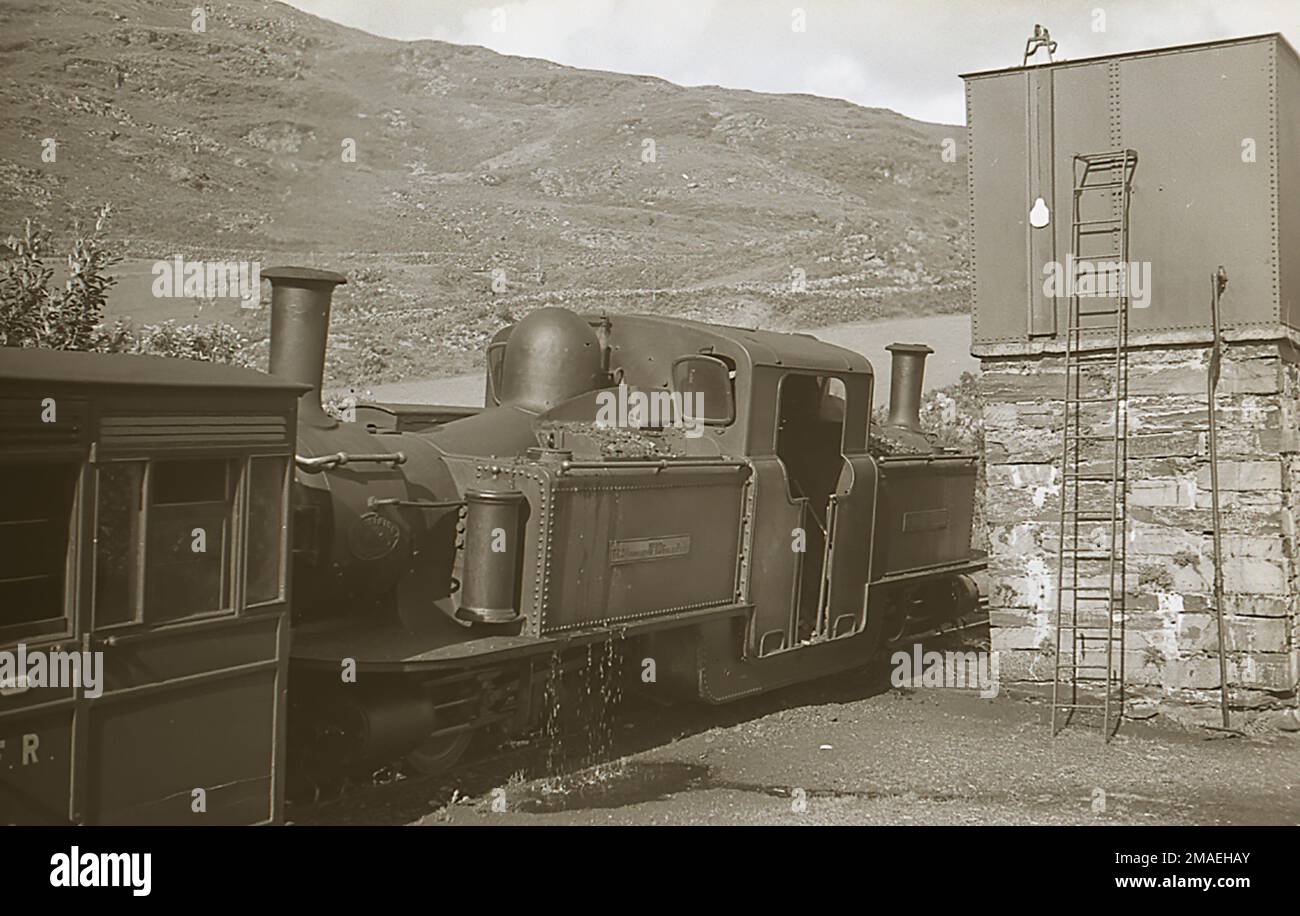
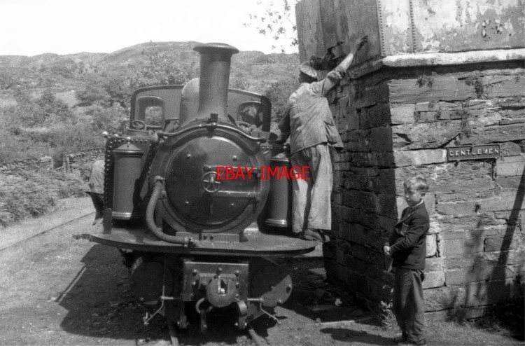
As always happens, no sooner had I printed the sides, glued them together and sprayed them black, when I found a superb picture showing the station side of the tank. The water gauge, a small bore pipe and a ladder are all perfectly clear, as is the mechanism that sits on top of the tank edge to support the float for the gauge. I'm not clear what that small pipe is, I think it is too low on the tank to be a fill pipe, but there is a "Gentlemen" sign on that wall on another photo, so I wonder if it is actually a supply pipe to the Gents facilities? Anyway, a few minutes later I found another picture which shows the discharge pipe on the tank front. Although not so clear, it shows enough to be able to guess at things.
The tank side picture is an Alamy one covered in their copyright watermarks, so I probably shouldn't copy it on here, but the URL is https://c8.alamy.com/comp/2MAEHAY/ffest ... MAEHAY.jpg.
Similarly the other picture is a postcard on Ebay, and the link is https://i.ebayimg.com/images/g/5u4AAOSw ... -l1600.jpg.
The only thing is that these two tanks appear to be different, the rivetting and supports are different between the two, but both predate the current modern tank. Because I'm not actually building a Ffestiniog station, it doesn't matter enough to me to redraw and reprint the tank at this point, so I'm going to fit these details to the tank I've already built based on Trevors design.
I started with Trevor's flat blank panels for the stone work base but after importing the stl's in SketchUp, I modified the corners to a plain chamfer rather than his stepped joints because printing those and cleaning them up would be a pain. So I drew a slab of the correct plan dimensions and 4mm thick and then I drew horizontal guide lines at 6.5mm vertical spacing on one face.
Using the "freehand " drawing tool in SketchUp, I simply drew roughly equal shaped and sized 2D stones, in between the guide lines, taking care to get headers and stretchers at opposite ends of each row.
- Screenshot 2023-12-24 07.29.32.png (223.75 KiB) Viewed 10310 times
The next step was to randomly pull up a selection of stones using the SU push-pull tool.
- Screenshot 2023-12-24 07.41.07(3).png (106.37 KiB) Viewed 10310 times
- Screenshot 2023-12-24 07.42.04.png (82.67 KiB) Viewed 10310 times
- Screenshot 2023-12-27 18.55.54.png (97.83 KiB) Viewed 10310 times
Once glued, I used some "Stonelux" Cotswold paint with fine sand mixed in to give a rough finish and then washed it with Citadel "Agrax Earthshade" to give a random effect.
- IMG_0569.jpg (590.7 KiB) Viewed 10310 times
Trevor has said that his model is based on the early version of the water tank. Not being a specific Ffestiniog modeller, I have only random pictures of the line and no good pictures of the water tank at any period. Looking online several pictures crop up showing the modern tank with pressed steel sides and twin discharge pipes, and there are a few which show partial side views of earlier tanks but with little detail. Now, in his stl zip file, Trevor has a water level gauge but no indication as to where it goes, and there is no detail of the discharge pipe, Oh, and shouldn't there be a ladder? Trevor does make mention of a supply feed pipe and one of the pictures that I found shows a pipe hooked over the back LH side of the tank, so far so good, but that picture also shows a vertical row of rivets on the tank side, not far from the back edge of the tank, which are not on Trevor's drawings. http://www.hall-royd-junction.co.uk/Rai ... _1966.html
So with the lack of any further information, I used Trevor's tank sides and printed them, intending to work out some details subsequently.
- IMG_0572.jpg (363.21 KiB) Viewed 10310 times
As always happens, no sooner had I printed the sides, glued them together and sprayed them black, when I found a superb picture showing the station side of the tank. The water gauge, a small bore pipe and a ladder are all perfectly clear, as is the mechanism that sits on top of the tank edge to support the float for the gauge. I'm not clear what that small pipe is, I think it is too low on the tank to be a fill pipe, but there is a "Gentlemen" sign on that wall on another photo, so I wonder if it is actually a supply pipe to the Gents facilities? Anyway, a few minutes later I found another picture which shows the discharge pipe on the tank front. Although not so clear, it shows enough to be able to guess at things.
The tank side picture is an Alamy one covered in their copyright watermarks, so I probably shouldn't copy it on here, but the URL is https://c8.alamy.com/comp/2MAEHAY/ffest ... MAEHAY.jpg.
Similarly the other picture is a postcard on Ebay, and the link is https://i.ebayimg.com/images/g/5u4AAOSw ... -l1600.jpg.
The only thing is that these two tanks appear to be different, the rivetting and supports are different between the two, but both predate the current modern tank. Because I'm not actually building a Ffestiniog station, it doesn't matter enough to me to redraw and reprint the tank at this point, so I'm going to fit these details to the tank I've already built based on Trevors design.
