Page 23 of 46
Re: Llewellyn Loco Works #1
Posted: Thu Sep 19, 2019 9:57 pm
by Hydrostatic Dazza
In the drought stricken Queensland (all of Australia) there is progress on the front foot plate.
Holes all drilled and 10 BA threads done.
A bit more milling and it will be done.


Re: Llewellyn Loco Works #1
Posted: Fri Sep 20, 2019 10:23 pm
by DonW
Hi Dazza
That casting looks very good. Did you make a master first? That will be bolted down onto the footplate you are making all looking very neat,
Don
Re: Llewellyn Loco Works #1
Posted: Fri Sep 20, 2019 11:01 pm
by Hydrostatic Dazza
DonW wrote: ↑Fri Sep 20, 2019 10:23 pm
Hi Dazza
That casting looks very good. Did you make a master first? That will be bolted down onto the footplate you are making all looking very neat,
Don
I draw the part in 3D and checked all in my full assembly model. Every part is done this way and then converted to a 2D workshop drawing. I drew another 3D part with some machining allowance added and then sent that file (STL version) to Mike at Stannier Engineering in NewZealand and he prints the wax part and the foundry make the shell mold with the wax and then do the investment casting. Then the postman delivers it to my door. The process takes 2-3 weeks. I have done this for the steam chest covers and the expansion link supports. Pics of this earlier in this thread some where. This all takes time but when the loco is completed and running there will be a full set of proven and accurate drawings for every part, without all the made up bits and vagaries and ommissions that I have have suffered in previous drawings.

Re: Llewellyn Loco Works #1
Posted: Fri Sep 20, 2019 11:03 pm
by Hydrostatic Dazza
1001 uses for small cut off discs. I simply love em.

Re: Llewellyn Loco Works #1
Posted: Sat Sep 21, 2019 1:02 pm
by DonW
[/quote]
I draw the part in 3D and checked all in my full assembly model. Every part is done this way and then converted to a 2D workshop drawing. I drew another 3D part with some machining allowance added and then sent that file (STL version) to Mike at Stannier Engineering in NewZealand and he prints the wax part and the foundry make the shell mold with the wax and then do the investment casting. Then the postman delivers it to my door. The process takes 2-3 weeks. I have done this for the steam chest covers and the expansion link supports. Pics of this earlier in this thread some where. This all takes time but when the loco is completed and running there will be a full set of proven and accurate drawings for every part, without all the made up bits and vagaries and ommissions that I have have suffered in previous drawings.
[/quote]
Thanks Dazza. I didn't realise they could print off the wax part from a drawing to such quality. I know people have been 3D printing master but thought these needed a fair bit of cleaning up.
Don
Re: Llewellyn Loco Works #1
Posted: Sat Sep 21, 2019 9:08 pm
by Hydrostatic Dazza
Don, go here
https://www.flickr.com/photos/151366293 ... 945260417/
for examples of the detail possible, note the small text on the castings.
The possibilities opening up are immense for model engineering.
Re: Llewellyn Loco Works #1
Posted: Sat Sep 21, 2019 9:18 pm
by Hydrostatic Dazza
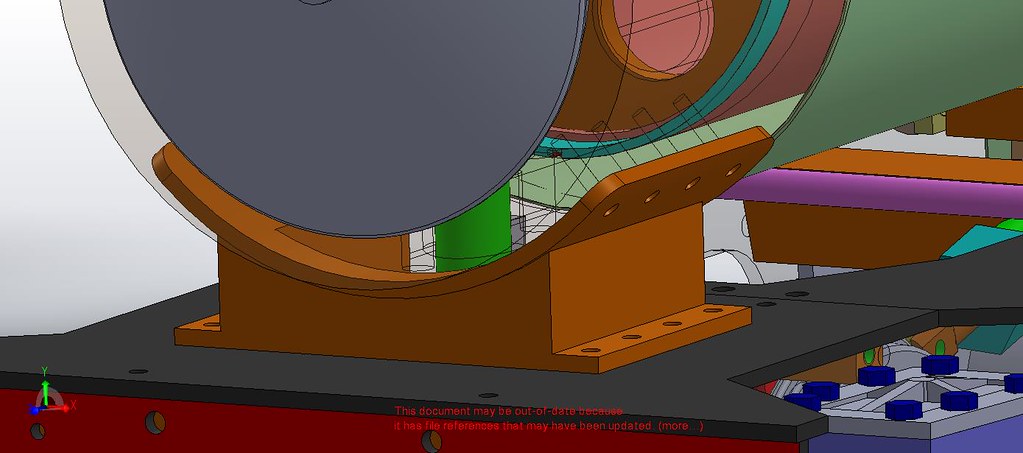
At the world wide head quarters of the Llewellyn Locomotive Works the drawing staff generated a plot to chain drill the front foot plate. It may seem fussy but it makes the final hand filing smooth and easy. One has to love DRO on the mill drill.
 After zero progress on the little loco and the POR garden railway it was nice to bolt this part on with 8 BA hex. No slotted screws are allowed to be seen on the exterior of this loco.
 Saddle casting and the completion of the cab foot plate are the next steps, then the smoke box so the boiler can be trial fitted to the frames.
Re: Llewellyn Loco Works #1
Posted: Sat Sep 21, 2019 9:20 pm
by tom_tom_go
That looks the nuts Dazza!
Re: Llewellyn Loco Works #1
Posted: Sun Sep 22, 2019 10:47 pm
by Hydrostatic Dazza
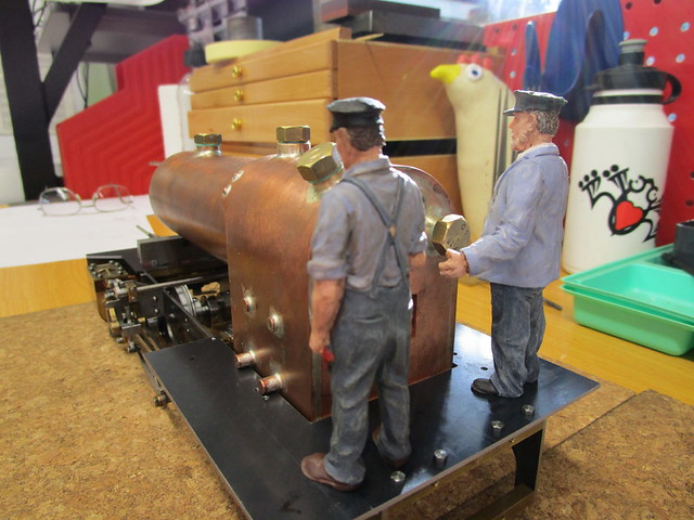
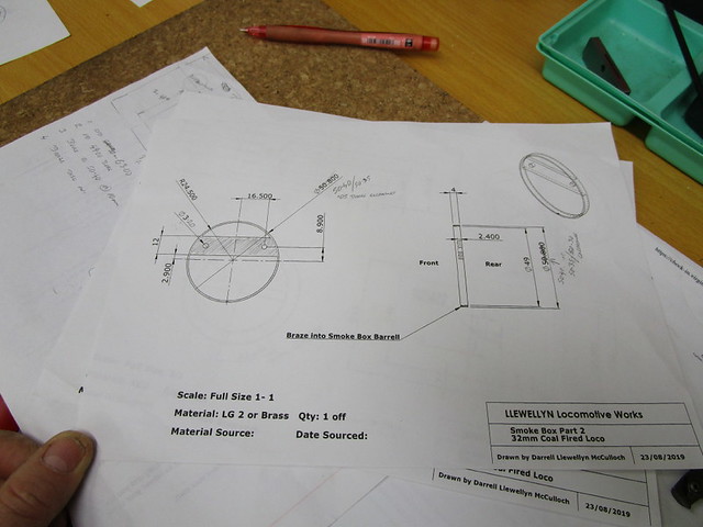
The head fitter and his side hand , or rather paw are pondering the smoke box. The drawing office has generated the required drawings and the materials are to hand.


Re: Llewellyn Loco Works #1
Posted: Sun Sep 22, 2019 10:51 pm
by Hydrostatic Dazza
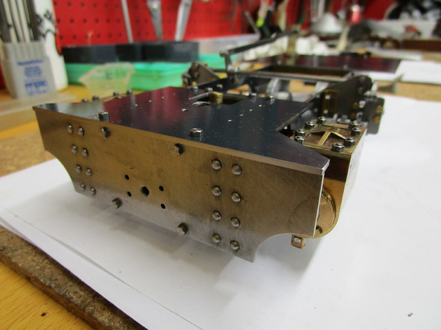
Chain drill the cab foot plate via DRO
 The loco crew called into the erection shop and had a look over the loco and made some comments about how some of servos will get under foot when they are fitted.

Re: Llewellyn Loco Works #1
Posted: Mon Sep 23, 2019 8:04 am
by DonW
And finding somewhere to place the Gas tank as well as the servos.
Lovely work. I assume you find chain drilling a better option than milling a slot.
Don
Re: Llewellyn Loco Works #1
Posted: Mon Sep 23, 2019 11:21 am
by tom_tom_go
This little dragon will be coal fired Don.
Re: Llewellyn Loco Works #1
Posted: Mon Sep 23, 2019 9:58 pm
by Hydrostatic Dazza
DonW wrote: ↑Mon Sep 23, 2019 8:04 am
And finding somewhere to place the Gas tank as well as the servos.
Lovely work. I assume you find chain drilling a better option than milling a slot.
Don
This fella will be coal fired for the full experience and atmosphere. 
I have a servo under the front foot plate for the cylinder drains. The reverser one will be in the half length R/H tank. The throttle one will have to be on the foot plate. I am also contemplating a servo to flip the fire door, to have better control of firing, cool the fire when standing or shunting. (in the cab) Not sure if it will be of any use but heaps of fun. Also one servo for the whistle which I hope to mount under the right side of the cab and the whistle is a pretend WHB air reservoir under the running board and tank.
I could mill, but the corners will still need a file unless you use a very small diameter cutter. I drilled and then filed it with the largest Mill files I had and checked it for dimensions and got all to 0.10mm . Filing is my daily work. It did not take long.
Re: Llewellyn Loco Works #1
Posted: Mon Sep 23, 2019 10:14 pm
by Hydrostatic Dazza
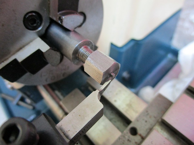
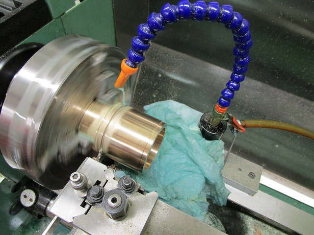
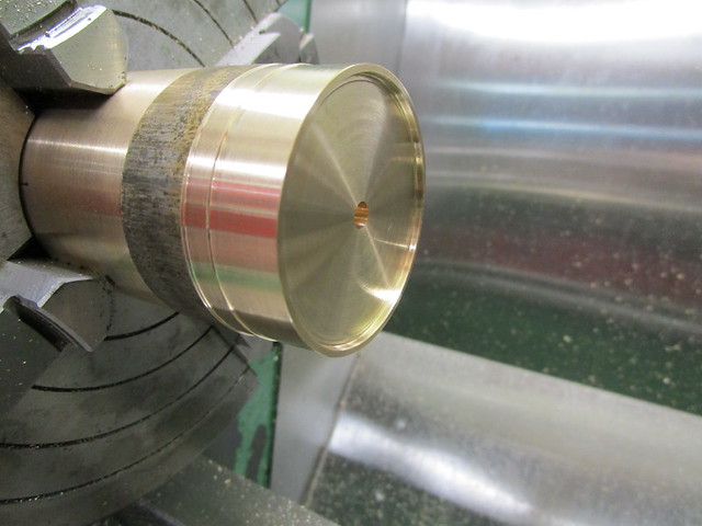
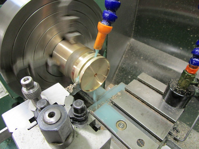
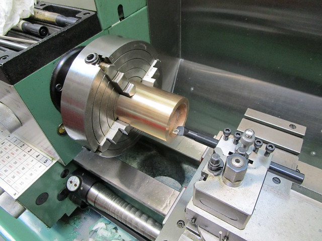
In hindsight I would have recessed the front tube plate deeper into the boiler barrel so the smoke box could be attached in a more traditional method, of rivets, screws etc but ................... So I have have hatched a plan to use the super heater attachments to pull and secure the smoke box to the barrel. Unlike the original (vague) drawings I am going for a fixed smoke box/boiler to the saddle and allow the expansion back wards in the frames, as like full size locos. Fixed at the rear and expansion movement forwards into the fixed smoke box/saddle seems a strange way to do it ? ! Considering that joint will foul up, even seize with the muck in the box and or keeping the joint air tight for good steaming, it just did not make sense. A reminder it is all a design and metal working exercise for the locos to come. The material is LG2 bronze a friend had left over, in payment for this material I brazed up some more full size loco motion oil pots that were needed as spares for the Rattler's 974 and 967.

Re: Llewellyn Loco Works #1
Posted: Thu Sep 26, 2019 3:15 pm
by bambuko
I wish there was
"like" button on this forum, to show appreciation for your posts

...
so here it is instead:

Re: Llewellyn Loco Works #1
Posted: Thu Sep 26, 2019 10:09 pm
by Hydrostatic Dazza
bambuko wrote: ↑Thu Sep 26, 2019 3:15 pm
I wish there was
"like" button on this forum, to show appreciation for your posts
...
so here it is instead: