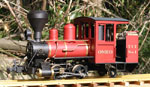

The first photo shows the passenger and van/cab sections spliced together to make one side. Extra boards were scribed into the ply to help unify the appearance, as the van had narrow boards and the carriage had wide ones as supplied.

The next photo shows the floors spliced together and the underframe from the carriage lengthened, after the electrickery was installed. The speed control, motor and gearbox are laid out in a mixture of the arrangements of the other railmotors.

This photo shows the assembled model ready for the paintshop. To make painting and servicing easy, the roof, body and underframe are screwed together and can be separated as needed.

This photo shows the lighting arrangement under the roof. I don't run models in the dark, but decided to fit simple lighting this time. If nothing else, it reminds me to turn off the power so the batteries don't go flat in storage. Storing batteries when flat is not good for them.... The plug and resistors are in the closed van section, so haven't been hidden. The passenger and cab wiring is hidden by conduit made from some channel shaped polystyrene. The headlight is a high output golden white LED, which is bright enough to cast shadows at night. The passenger light is a standard yellow LED, giving the effect of a low wattage light powered from the low power electrical system of the railmotor.

This photo shows the controls under the floor of the model. I decided to experiment with remote controlling one railmotor from the controls of the other when coupled together. The controls are as follows; top right - speed control, bottom right -reversing switch, centre top - charge/run switch, centre middle - remote control selection, centre bottom - charging socket. The remote cable to Railmotor no. 1 plugs into the 3 pin socket at left. This is wired such that it can't be connected up the wrong way. When remote is selected, the motor in Railmotor no. 3 is connected to this socket, disabling the reverse switch and speed control, so that speed and direction come from the controls in the other railmotor.

Railmotor 3 went through the paint shop three weeks ago, but has been waiting for the sun to show itself for a portrait to be taken.

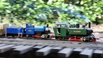
This is what the two railmotors look like when running coupled together, although from this angle, RM1 just looks like a large passenger trailer. In real life a truck chassis based railmotor like these would not have mu controls. The trailing unit would be shut down and the gearbox would be in neutral, with the leading unit doing all the work. The VR sometimes ran single ended AEC railmotors this way on shuttle services to save turning them at each end of the run and I'd imagine the Colonel Stephens railmotor pairs were operated the same way.

TVT History
Traffic on the mining branchline continues to fall and the one man crew now frequently outnumbers the passengers, so the only thing keeping the service open is the postal subsidy from the PMG. The workshops had started building a large railmotor trailer, but have now turned out Motor No. 3 to reduce costs further, as it will use less petrol with no trailer to pull.
There had been talk that Motor No. 1 would be rebuilt, but the Education Dept. were prepared to pay for a daily school train to bring children from outlying farms into school and it has instead been allocated to this service.
The works engineer claimed the small mail trailer that was used with Motor No. 1 and it now appears with the works motor as a tool van for the track gang.
Regards,
Graeme




 No. 3 also has upholstered seats, not visible in the photo.....