I have modified Rick's programme (what is called a "sketch" in Arduino) to work with the ESP32C3 boards which I purchased online.
Otherwise electronically it is a copy of Rik's work. If anyone is interested in the "sketch" I can add it.
Here is a short video to demonstrate all 10 of them working on the bench: https://www.dropbox.com/scl/fi/j6y3h94m ... ezbxc&dl=0
You can see the lamps showing red for stop and white for clear.
I have to print off 10 sockets to mount in the garden before I can show them working on the railway.
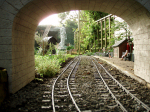
Here are photos of the "caution" signals I made to go alongside the steps where the footpath crosses the railway. These don't move, and are intended as fixed "caution" signals with "W" written across them to indicate that the driver should sound a whistle. The green light indicates "caution" (well it did in 1880):
- IMG_4345.jpeg (2.97 MiB) Viewed 41099 times
- IMG_4346.jpeg (2.31 MiB) Viewed 41099 times
You might also notice that the two types of signal are slightly different - because after printing the 10 disc signals I found a drawing of these signals and modified the drawing to more accurately reflect the prototype. The handrail, the footplate, and the footplate brackets are different. Also the base of the column has the correct webs and ornamentation. I have not implemented the scalloping on the column itself.
So now on to the double arm signals.
I am hoping to use a different approach to these by using an ESP32C3 board to act as a transmitter using low energy Bluetooth, and another ESP32C3 board to act as a BLE (Bluetooth low energy) receiver to decode the bluetooth signal and control the two servos on the signal. I will let you know if I mange to get that to work.
Trevor